AIR CONDITIONING SYSTEM
-
FUNCTION OF MAIN COMPONENTS
-
The air conditioning system consists of the following parts:
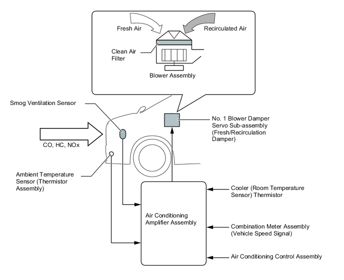
Component Function Ambient Temperature Sensor (Thermistor Assembly) Detects ambient temperature and outputs it to the air conditioning amplifier assembly. Air Conditioning Pressure Sensor Detects the refrigerant pressure and sends the data to the air conditioning amplifier assembly. Smog Ventilation Sensor*1 Detects harmful elements such as CO, HC, and NOx in the air outside of the vehicle and sends the data to the air conditioning amplifier assembly. Solar Sensor (Automatic Light Control Sensor) Detects the changes in the amount of solar energy and sends the data to the air conditioning amplifier assembly via the main body ECU (multiplex network body ECU). Cooler (Room Temperature Sensor) Thermistor Detects the cabin temperature and sends the data to the air conditioning amplifier assembly. Cooler (No. 2 Room Temperature Sensor) Thermistor Detects the cabin temperature and sends the data to the air conditioning amplifier assembly. Compressor with Pulley Assembly Performs suction, compression and discharge of refrigerant gas. Front Air Conditioning Unit Evaporator Temperature Sensor (No. 1 Cooler Thermistor) Detects the temperature of the cooled air immediately past the No. 1 cooler evaporator sub-assembly in the form of resistance changes and sends the data to the air conditioning amplifier assembly. No. 1 Air Conditioning Radiator Damper Servo Sub-assembly Damper Servo (Mode Switching) Controlled by the air conditioning amplifier assembly to move the mode control damper and switch the air outlet mode. Damper Servo (Driver Side Air Mix) Controlled by the air conditioning amplifier assembly to move the driver seat air mix control damper and adjust the driver side outlet air temperature. Damper Servo (Front Passenger Side Air Mix) Controlled by the air conditioning amplifier assembly to move the front passenger seat air mix control damper and adjust the front passenger side outlet air temperature. No. 1 Blower Damper Servo Sub-assembly (Fresh/Recirculation Damper) Driven by the air conditioning amplifier assembly to move the fresh/recirculation damper. Blower Motor with Fan Sub-assembly Driven according to the target airflow volume calculated by the air conditioning amplifier assembly to blow air toward the cabin and circulate the air inside the cabin. PTC Heater (Quick Heater Assembly)*2 Generates heat according to the current from the PTC heater relay controlled by the air conditioning amplifier assembly to warm the air inside the front air conditioning unit. Rear Cooling Unit Assembly Rear Evaporator Temperature Sensor (No. 2 Air Conditioning Harness Assembly) Detects the temperature of the cooled air immediately past the rear evaporator sub-assembly in the form of resistance changes and sends the data to the air conditioning amplifier assembly. Rear No. 1 Cooling Unit Damper Servo Sub-assembly Damper Servo (Air Mix) Controlled by the air conditioning amplifier assembly to move the rear air mix control damper and adjust the outlet air temperature. Rear No. 2 Cooling Unit Damper Servo Sub-assembly Damper Servo (Mode Switching) Controlled by the air conditioning amplifier assembly to move the rear mode control damper and switch the air outlet mode. Blower Motor Control Receives airflow volume signals from the air conditioning amplifier assembly and controls the rear blower motor with fan sub-assembly. Rear Blower Motor with Fan Sub-assembly Driven according to the signal from the blower motor control to blow air toward the cabin and circulate the air inside the cabin. No. 1 Ion Generator Sub-assembly*3 Generates nanoeTM*4.
No. 2 Ion Generator Sub-assembly*3 Generates nanoeTM*4.
Air Conditioning Control Assembly Allows operation and adjustment of the front and rear air conditioning systems via switches. Integration Control and Panel Assembly Allows operation and adjustment of the rear air conditioning system via switches. Air Conditioning Amplifier Assembly Transmits and receives data to and from the switches and sensors, and controls the air conditioning system. Combination Meter Assembly Multi-information Display
-
Turns nanoeTM*4 operation mode on and off based on steering switch assembly operations.
-
Displays the condition of the rear automatic air conditioning system.
-
When power decreases, displays a message that air conditioning control is restricted.
Tech Tips
*1: Models with automatic recirculation control
*2: Models for China and Russia
*3: Models with nanoeTMgenerator
*4: nanoeTMis a trademark of Panasonic Corporation.
-
-
-
SYSTEM CONTROL
-
The air conditioning system uses the following controls:
Control Outline Neural Network Control This control is capable of effecting complex control by artificially simulating the information processing method of the nervous system of living organisms in order to establish a complex input/output relationship that is similar to that of a human brain. Outlet Air Temperature Control Based on the temperature set at the temperature control switch, the neural network control calculates the outlet air temperature based on the input signals from various sensors. The temperature setting for the driver, front passenger and rear passengers is controlled independently in order to provide 3 vehicle interior temperature zones, one each for the driver, front passenger and rear passengers. Thus, air conditioning control that accommodates occupant preferences has been achieved. Blower Control Controls the blower motor in accordance with the airflow volume that has been calculated by neural network control based on the input signals from various sensors. Air Outlet Control Automatically switches the air outlets in accordance with the outlet mode that has been calculated by neural network control based on the input signals from various sensors. In accordance with the engine coolant temperature, ambient temperature, amount of sunlight, required blower, outlet temperature and vehicle speed conditions, this control automatically switches the blower outlet to FOOT/DEF mode to prevent the windows from becoming fogged when the ambient temperature is low. Air Inlet Control Automatically controls the air inlet control damper to achieve the calculated outlet air temperature that is required. Drives the No. 1 blower damper servo sub-assembly (fresh/recirculation damper) in accordance with the operation of the air inlet control switch and moves the dampers to the FRESH or RECIRC position. Automatic Recirculation Control*1 Automatically changes the air inlet mode to fresh air or recirculate mode according to the level of harmful elements in the outside air, cabin temperature, ambient temperature and vehicle speed. Compressor Control The air conditioning amplifier assembly calculates the target evaporator temperature (which is calculated by the room temperature sensor, ambient temperature sensor, and solar sensor) and the actual evaporator temperature that is detected by the evaporator temperature sensor in order to control the compressor. PTC Heater Control*2 When the engine switch is turned on (IG), and the blower motor is turned on, the air conditioning amplifier assembly turns on the PTC heater (quick heater assembly) if the following conditions are met.
-
Engine coolant temperature is below specified temperature.
-
Ambient temperature is below specified temperature.
-
Tentative air mix damper opening angle is above the specified value (MAX HOT).
ECO Drive Mode Control When set to ECO drive mode, the air conditioning amplifier assembly decreases the blower speed. Electric Power Control
-
When the vehicle voltage is below the specified level, the air conditioning amplifier assembly saves the power source of some systems in accordance with the voltage signal.
-
When the electric power control is operating, the combination meter assembly warns the driver by indicating a message on the multi-information display.
Ion Generator Control*3 When nanoeTM*4 operation mode is on, the ion generator sub-assembly operates together with the rotation of the blower motor.
Rear Window Defogger Control Controls the rear defogger system according to rear window defogger switch operation. For details, see the WINDOW / GLASS section. Front Wiper Deicer Control*5 Controls the front wiper deicer system according to front wiper deicer switch (outer mirror heater switch assembly) operation. For details, see the WINDOW / GLASS section. Tech Tips
-
*1: Without standard grade
-
*2: Models for China and Russia
-
*3: Models with nanoeTMgenerator
-
*4: nanoeTMis a trademark of Panasonic Corporation.
-
*5: Models with front wiper deicer system
-
-
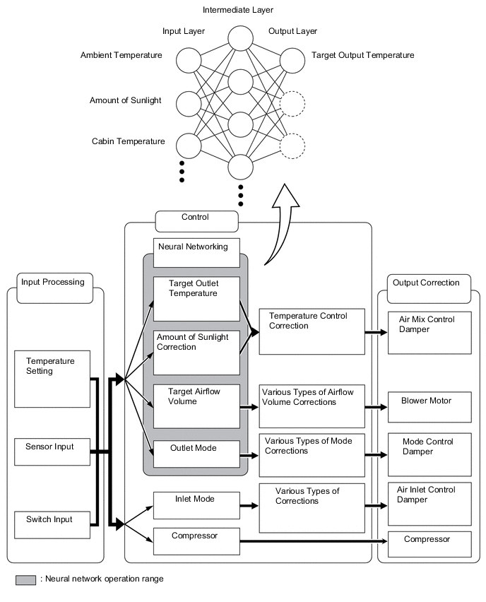
Neural Network Control
-
In the previous automatic air conditioning system, the air conditioning amplifier assembly determined the required outlet air temperature and blower air volume in accordance with a calculation formula that had been obtained based on information received from the sensors. However, because the senses of a person are rather complex, a given temperature is sensed differently, depending on the environment in which the person is situated. For example, a given amount of solar radiation can feel comfortably warm in a cold climate, but extremely uncomfortable in a hot climate. Therefore, as a technique for performing a high level of control, a neural network is used in the automatic air conditioning system. With this technique, the data that has been collected under varying environmental conditions is stored in the air conditioning amplifier assembly, which effects control to provide enhanced air conditioning comfort.
-
The neural network control consists of neurons in an input layer, an intermediate layer, and an output layer. The input layer neurons process the input data of the ambient temperature, the amount of sunlight and the cabin temperature based on the outputs of the switches and sensors, and output them to the intermediate layer neurons. Based on this data, the intermediate layer neurons adjust the strength of the links among the neurons. The sum of this data is then calculated by the output layer neurons in the form of the required outlet temperature, solar correction, target airflow volume and outlet mode control volume. Accordingly, the air conditioning amplifier assembly controls the servo motors and blower motor with fan sub-assembly in accordance with the control volumes that have been calculated by the neural network control.
-
-
Automatic Recirculation Control
-
When the automatic recirculation control is operating, the air conditioning amplifier assembly automatically changes the air inlet mode to the fresh air or recirculate air mode based on signals from the smog ventilation sensor, vehicle speed signal, ambient temperature sensor, and room temperature sensors when the AUTO air inlet mode is selected.
-
The air conditioning amplifier assembly detects harmful elements (CO, HC, and NOx) based on the smog ventilation sensor signal and vehicle speed signal, and automatically switches the air inlet mode to the recirculate air mode to prevent such harmful elements from entering the cabin.
-
The air conditioning amplifier assembly detects cabin temperature based on a room temperature sensor signal and automatically switches the air inlet mode to the recirculate air mode to prevent the cabin temperature from becoming too high.
-
The air conditioning amplifier assembly detects the ambient temperature based on an ambient temperature sensor signal and automatically switches the air inlet mode to the fresh air mode to prevent the windshield from fogging up.
-
-
-
ECO Drive Mode Control
-
Under the control of the ECO drive mode, the air conditioning amplifier assembly restricts the air conditioning system performance under specified conditions, thus improving fuel economy.
-
The ECO drive mode control is activated when the combination switch assembly (ECO mode switch) is operated, and then restricts the air conditioning system performance as described below:
Control Outline Inside/outside Air Switch Control Automatically switches the air inlet port to the internal air circulation mode when the ambient temperature is equal to or higher than a predetermined temperature and reduces the power consumption. Blower Level Control Sets the blower level in AUTO mode lower than normal, and suppresses the power consumption.
-
-
-
DIAGNOSIS
-
The air conditioning amplifier assembly has a self-diagnosis function. It stores any operation malfunctions in the air conditioning system or heater system in memory in the form of Diagnostic Trouble Codes (DTCs). For details, refer to the Repair Manual.
-