METER / GAUGE SYSTEM
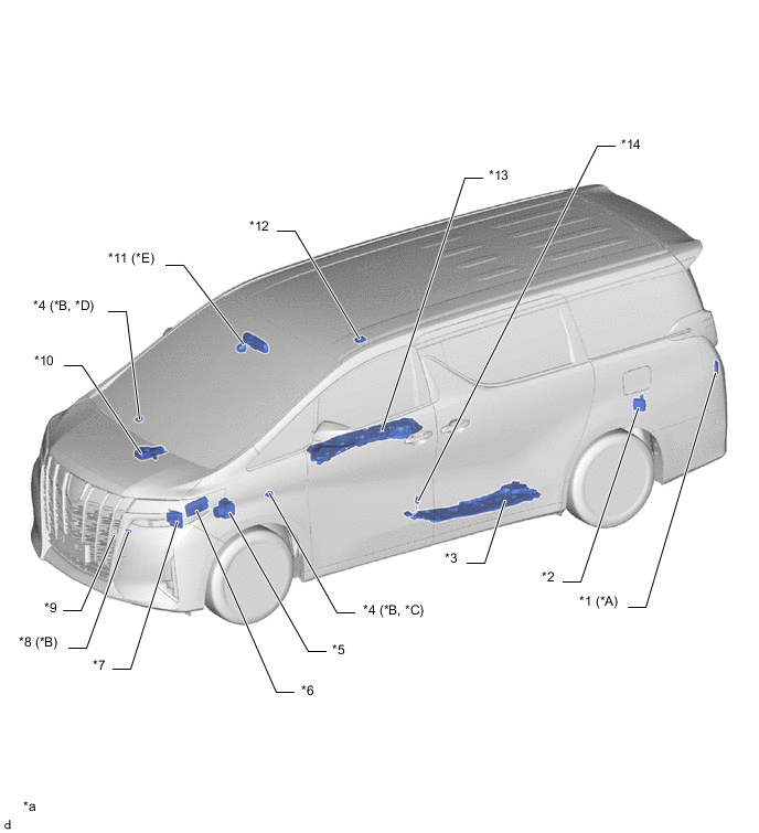
| *A | Models with Blind Spot Monitor System | *B | Models with 2GR-FKS Engine |
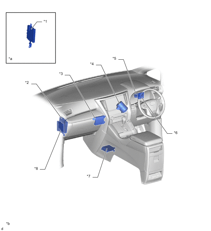
| *C | LHD Models | *D | RHD Models |
| *E | Models with Automatic High Beam System | - | - |
| *1 | Blind Spot Monitor Sensor LH | *2 | Parking Brake ECU Assembly |
| *3 | Slide Door Motor Unit LH
|
*4 | Vacuum Warning Switch Assembly |
| *5 | Brake Actuator Assembly
|
*6 | ECM |
| *7 | Headlight Light Control ECU Sub-assembly LH | *8 | Oil Level Sensor |
| *9 | Engine Oil Pressure Switch Assembly | *10 | Brake Master Cylinder Reservoir Assembly
|
| *11 | Inner Rear View Mirror Assembly
|
*12 | Room Light Control Relay |
| *13 | Slide Door Motor Unit RH
|
*14 | Fuel Sender Gauge Assembly |
| *a | The illustrations shown are examples only. | - | - |
Figure 1. LHD Models
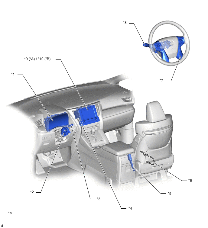
| *A | Models with Navigation Receiver Assembly | *B | Models with Radio and Display Receiver Assembly |
| *1 | Combination Meter Assembly | *2 | Spiral Cable with Sensor Sub-assembly |
| *3 | Trip Switch | *4 | Hazard Warning Signal Switch Assembly |
| *5 | Front Seat Inner Belt Assembly RH | *6 | Belt Warning Occupant Detection Sensor RH |
| *7 | Steering Pad Switch Assembly | *8 | Headlight Dimmer Switch Assembly |
| *9 | Navigation Receiver Assembly | *10 | Radio and Display Receiver Assembly |
| *a | The illustrations shown are examples only. | - | - |
Figure 2. RHD Models
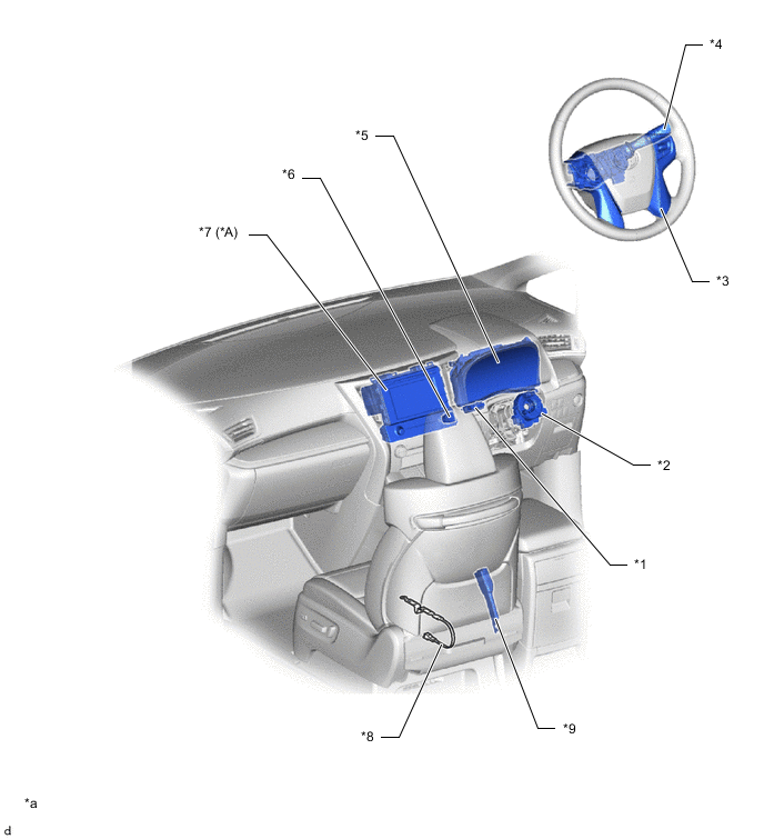
| *A | Models with Navigation Receiver Assembly | - | - |
| *1 | Trip Switch | *2 | Spiral Cable with Sensor Sub-assembly |
| *3 | Steering Pad Switch Assembly | *4 | Headlight Dimmer Switch Assembly |
| *5 | Combination Meter Assembly | *6 | Hazard Warning Signal Switch Assembly |
| *7 | Navigation Receiver Assembly | *8 | Belt Warning Occupant Detection Sensor LH |
| *9 | Front Seat Inner Belt Assembly LH | - | - |
| *a | The illustrations shown are examples only. | - | - |
Figure 3. LHD Models
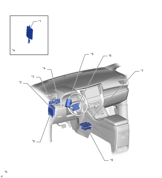
| *1 | Certification ECU (Smart Key ECU Assembly) | *2 | Engine Stop and Start ECU |
| *3 | Central Gateway ECU (Network Gateway ECU) | *4 | Clearance Warning ECU Assembly |
| *5 | Power Steering ECU Assembly | *6 | Air Conditioning Amplifier Assembly |
| *7 | Parking Assist ECU | *8 | Airbag ECU Assembly |
| *9 | Main Body ECU (Multiplex Network Body ECU) | - | - |
| *a | Refer to Service Bulletin for the installation position of the part. | *b | The illustrations shown are examples only. |
Figure 4. RHD Models
| *1 | Certification ECU (Smart Key ECU Assembly) | *2 | Engine Stop and Start ECU |
| *3 | Air Conditioning Amplifier Assembly | *4 | Power Steering ECU Assembly |
| *5 | Central Gateway ECU (Network Gateway ECU) | *6 | Clearance Warning ECU Assembly |
| *7 | Airbag ECU Assembly | *8 | Main Body ECU (Multiplex Network Body ECU) |
| *a | Refer to Service Bulletin for the installation position of the part. | *b | The illustrations shown are examples only. |