POWER DOOR LOCK CONTROL SYSTEM
Figure 1. LHD Models
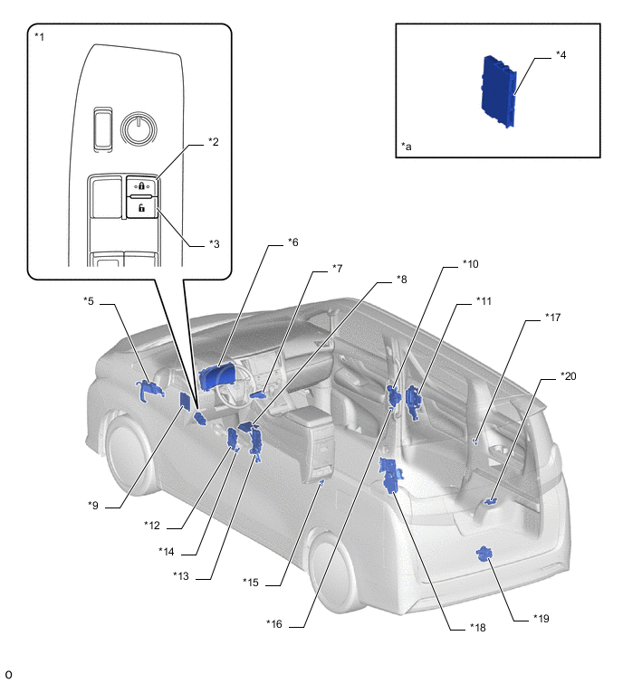
| *1 | Multiplex Network Master Switch Assembly | *2 | Lock Switch |
| *3 | Unlock Switch | *4 | Certification ECU (Smart Key ECU Assembly) |
| *5 | ECM | *6 | Combination Meter Assembly |
| *7 | Sub Battery (Door Control Battery) | *8 | Airbag ECU Assembly |
| *9 | Main Body ECU (Multiplex Network Body ECU) | *10 | Front Door Lock with Motor Assembly RH |
| *11 | Slide Door Handle Assembly RH | *12 | Front Door Lock with Motor Assembly LH |
| *13 | Slide Door Handle Assembly LH | *14 | Front Door Courtesy Light Switch Assembly LH |
| *15 | Rear Door Courtesy Light Switch Assembly LH | *16 | Front Door Courtesy Light Switch Assembly RH |
| *17 | Rear Door Courtesy Light Switch Assembly RH | *18 | Back Door Motor Unit
|
| *19 | Back Door Lock Assembly | *20 | Back Door Opener Switch Assembly |
| *a | Refer to the Service Bulletin for the installation of the part. | - | - |
Figure 2. RHD Models
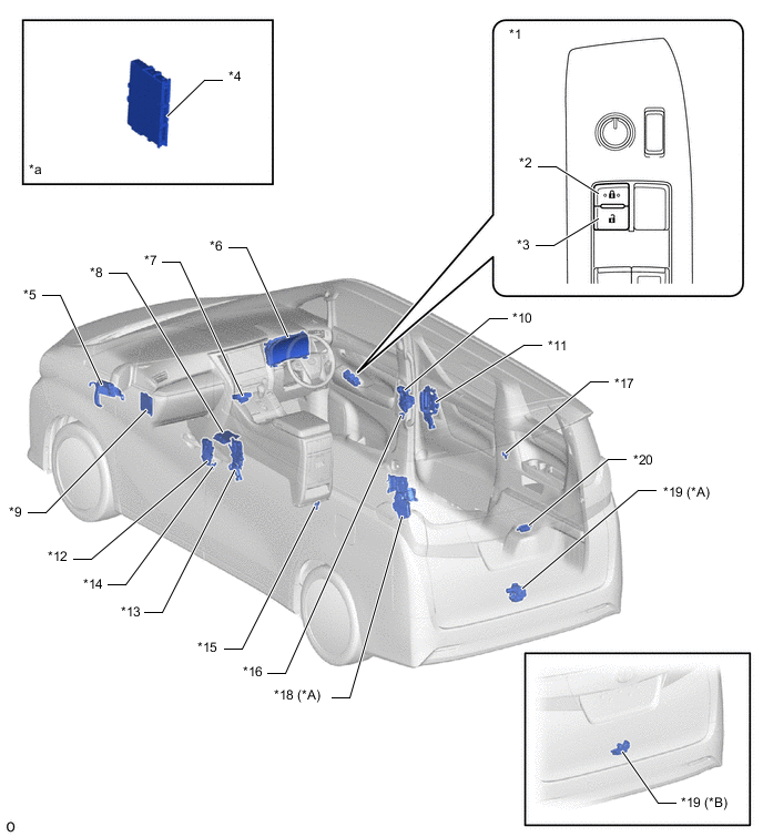
| *A | Models with Power Back Door | *B | Models without Power Back Door |
| *1 | Multiplex Network Master Switch Assembly | *2 | Lock Switch |
| *3 | Unlock Switch | *4 | Certification ECU (Smart Key ECU Assembly) |
| *5 | ECM | *6 | Combination Meter Assembly |
| *7 | Sub Battery (Door Control Battery) | *8 | Airbag ECU Assembly |
| *9 | Main Body ECU (Multiplex Network Body ECU) | *10 | Front Door Lock with Motor Assembly RH |
| *11 | Slide Door Handle Assembly RH | *12 | Front Door Lock with Motor Assembly LH |
| *13 | Slide Door Handle Assembly LH | *14 | Front Door Courtesy Light Switch Assembly LH |
| *15 | Rear Door Courtesy Light Switch Assembly LH | *16 | Front Door Courtesy Light Switch Assembly RH |
| *17 | Rear Door Courtesy Light Switch Assembly RH | *18 | Back Door Motor Unit
|
| *19 | Back Door Lock Assembly | *20 | Back Door Opener Switch Assembly |
| *a | Refer to the Service Bulletin for the installation of the part. | - | - |