SMART ENTRY AND START SYSTEM
Figure 1. Models with 2AR-FE Engine
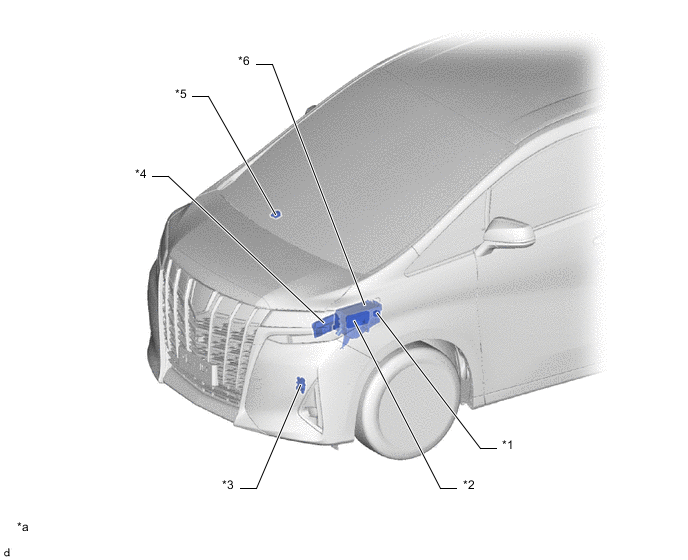
| *1 | No. 1 Starter Relay Assembly | *2 | No. 1 Integration Relay
|
| *3 | Park/Neutral Position Switch Assembly | *4 | ECM |
| *5 | Wireless Door Lock Buzzer | *6 | Engine Room Relay Block |
| *a | This illustration shown is an example only. | - | - |
Figure 2. Models with 2GR-FKS Engine
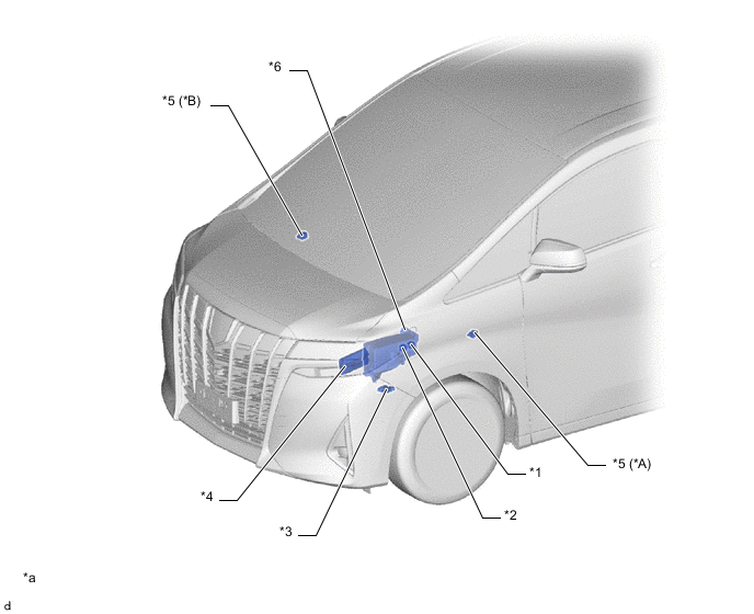
| *A | LHD Models | *B | RHD Models |
| *1 | No. 1 Starter Relay Assembly | *2 | IG2 Relay |
| *3 | Park/Neutral Position Switch Assembly | *4 | ECM |
| *5 | Wireless Door Lock Buzzer | *6 | Engine Room Relay Block |
| *a | This illustration shown is an example only. | - | - |
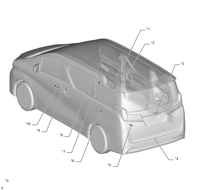
| *1 | Front Door Outside Handle Assembly RH
|
*2 | Rear Door Outside Handle Cover RH
|
| *3 | Back Door Opener Switch Assembly
|
*4 | Electrical Key Antenna |
| *5 | No. 3 Indoor Electrical Key Antenna Assembly | *6 | No. 2 Indoor Electrical Key Antenna Assembly |
| *7 | Door Control Receiver | *8 | No. 1 Indoor Electrical Key Antenna Assembly |
| *9 | Rear Door Outside Handle Cover LH
|
*10 | Front Door Outside Handle Assembly LH
|
| *a | This illustration shown is an example only. | - | - |
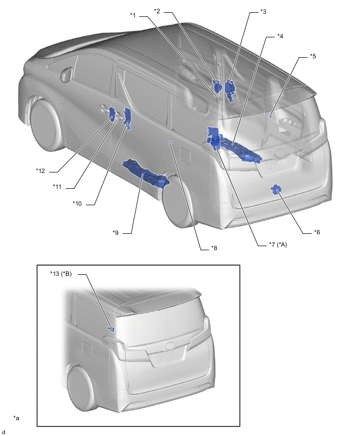
| *A | Models with Power Back Door System | *B | Models without Power Back Door System |
| *1 | Front Door Courtesy Light Switch Assembly RH | *2 | Front Door Lock with Motor Assembly RH
|
| *3 | Slide Door Handle Assembly RH
|
*4 | Slide Door Motor Unit RH
|
| *5 | Rear Door Courtesy Light Switch Assembly RH | *6 | Back Door Lock Assembly
|
| *7 | Back Door Motor Unit
|
*8 | Rear Door Courtesy Light Switch Assembly LH |
| *9 | Slide Door Motor Unit LH
|
*10 | Slide Door Handle Assembly LH
|
| *11 | Front Door Courtesy Light Switch Assembly LH | *12 | Front Door Lock with Motor Assembly LH
|
| *13 | Multiplex Network Door ECU | - | - |
| *a | This illustration shown is an example only. | - | - |
Figure 3. LHD Models
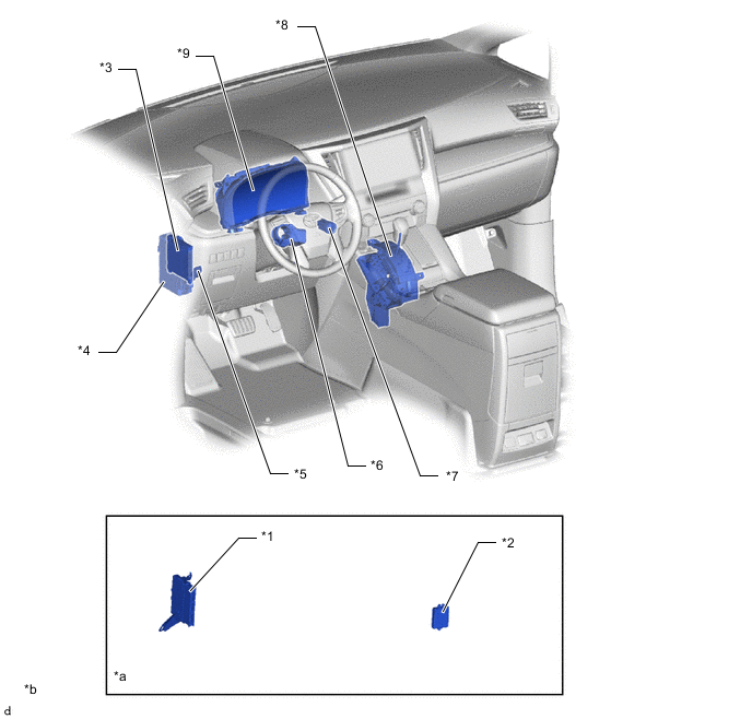
| *1 | Certification ECU (Smart Key ECU Assembly) | *2 | ID Code Box (Immobiliser Code ECU) |
| *3 | Main Body ECU (Multiplex Network Body ECU) | *4 | Junction Block Assembly LH
|
| *5 | Stop Light Switch Assembly | *6 | Steering Lock Actuator Assembly
|
| *7 | Engine Switch (Push Start Switch) | *8 | Shift Lock Control Unit Assembly
|
| *9 | Combination Meter Assembly | - | - |
| *a | Refer to Service Bulletin for the installation position of the parts. | *b | This illustration shown is an example only. |
Figure 4. RHD Models
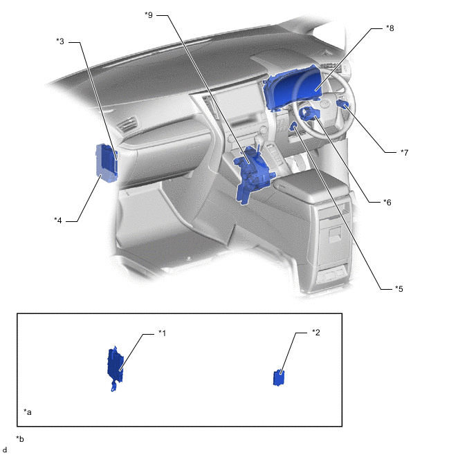
| *1 | Certification ECU (Smart Key ECU Assembly) | *2 | ID Code Box (Immobiliser Code ECU) |
| *3 | Main Body ECU (Multiplex Network Body ECU) | *4 | Junction Block Assembly LH
|
| *5 | Stop Light Switch Assembly | *6 | Steering Lock Actuator Assembly
|
| *7 | Engine Switch (Push Start Switch) | *8 | Combination Meter Assembly |
| *9 | Shift Lock Control Unit Assembly
|
- | - |
| *a | Refer to Service Bulletin for the installation position of the parts. | *b | This illustration shown is an example only. |