BLIND SPOT MONITOR SYSTEM
-
CONSTRUCTION
-
The blind spot monitor sensor consists of a millimeter wave radar circuit and signal processing circuit.
-
The millimeter wave radar uses frequencies in the 24 GHz band.
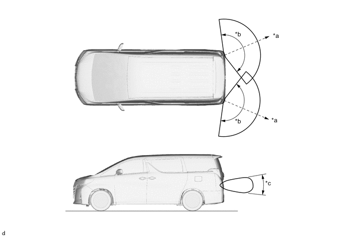
*a Distance: Approximately 70 m (230 ft.) *b Horizontal Angle: Approximately 150° *c Vertical Angle: Approximately 20° - -
-
The distance to the object, azimuth, and relative speed are calculated from the information that is provided by the reflected millimeter wave radar as described below.
Item Calculation Method Distance Calculated from the length of time that has elapsed from the time the waves of the millimeter wave radar have been emitted, until the reflected waves are received by the millimeter wave radar circuit. The distance is approximately 70 m (230 ft.). Azimuth Calculated from the reception angle of the reflected millimeter wave radar waves. The detection angle has a horizontal range of approximately 150° and a vertical range of approximately 20°. Relative Speed Calculated by utilizing the change (Doppler effect*) that occurs in the frequency of the reflected millimeter wave radar waves. Tech Tips
*: The Doppler effect causes the observer to perceive the radio waves emitted by a moving object to be a higher frequency as it approaches, and to be a lower frequency as it recedes. An SST is used if radar axis confirmation is needed. For details, refer to the Repair Manual.
-
-