TOYOTA PARKING ASSIST-SENSOR SYSTEM
-
FUNCTION OF MAIN COMPONENTS
Component Function Ultrasonic Sensors Detects the distance between the vehicle and an obstacle. Park/Neutral Position Switch Assembly Transmits the shift position signal to the ECM. Steering Pad Switch Assembly Transmits operation signals to the spiral cable with sensor sub-assembly. Spiral Cable with Sensor Sub-assembly Receives operation signals from the steering pad switch assembly and transmits them to the combination meter assembly. Clearance Warning ECU Assembly
-
Judges the approximate distance between the vehicle and an obstacle based on signals from the ultrasonic sensors. Output signals are sent to the combination meter assembly, navigation receiver assembly*1 or radio and display receiver assembly*2.
-
Sounds the No. 1 clearance warning buzzer.
Parking Assist ECU*3 Outputs the cooperative display video signal for the panoramic view monitor screen to the navigation receiver assembly based on signals from the clearance warning ECU assembly. Combination Meter Assembly Clearance Sonar Indicator Light Illuminates to inform the driver when the system operation conditions are met. Multi-information Display
-
Displays the location of the obstacle and the approximate distance between the vehicle and the obstacle.
-
Displays an indication of a malfunction or freezing of an ultrasonic sensor to inform the driver.
Master Warning Light Illuminates in accordance with the indication on the multi-information display. Navigation Receiver Assembly*1/Radio and Display Receiver Assembly*2
-
Displays the location of an obstacle and the approximate distance between the vehicle and the obstacle.
-
Displays an indication of a malfunction or freezing of an ultrasonic sensor to inform the driver.
-
The sound volume, distance required to sound the buzzer and distance required to trigger the display can be chosen on the setup screen for the TOYOTA parking assist-sensor system.
-
Transmits the setup signal for the TOYOTA parking assist-sensor system to the clearance warning ECU assembly.
ECM Transmits the shift position signal to the clearance warning ECU assembly. Brake Actuator Assembly
-
Skid Control ECU
Transmits received vehicle speed signals to the clearance warning ECU assembly. Air Conditioning Amplifier Assembly Receives outside air temperature information from the air conditioning amplifier assembly and transmits it to the clearance warning ECU assembly. Network Gateway ECU*3 Relays and transmits each CAN communication data signal. No. 1 Clearance Warning Buzzer Sounds to inform the driver according to the distance to the obstacle. DLC3 System diagnosis is performed by using the diagnostic tool. *1: Models with navigation receiver assembly
*2: Models with radio and display receiver assembly
*3: Models with panoramic view monitor system
-
-
OPERATING CONDITION
-
Operating Condition
-
The operating condition of each sensor differs according to its installed position as shown in the table below:
Installation Position Operating Condition Front Corner (FL Sensor, FR Sensor)
-
Engine switch is on (IG).
-
System is activated.
-
Shift lever is not in P.
-
Vehicle speed is approximately 10 km/h (6 mph) or less. (Shift lever is not in R.)
Rear Corner (RL Sensor, RR Sensor)
-
Engine switch is on (IG).
-
System is activated.
-
Shift lever is in R.
Rear Center (RLC Sensor, RRC Sensor)
-
Engine switch is on (IG).
-
System is activated.
-
Shift lever is in R.
-
-
-
Detection Area
-
The detection areas of the ultrasonic sensor are as shown in the following illustration.
-
These detection areas are applicable when positioning a 60 mm (2.36 in.) diameter pole parallel or perpendicular to the ground. The ranges vary depending on the measuring method and type of obstacle.
Figure 1. Corner Area
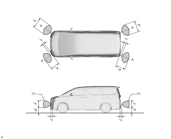
*a Approximately 650 mm to 700 mm (25.6 in. to 27.6 in.) *b Approximately 810 mm (31.9 in.) *c Approximately 200 mm (7.87 in.) *d Approximately 600 mm (23.6 in.) *e Approximately 370 mm to 380 mm (14.6 in. to 15.0 in.) *f Approximately 470 mm (18.5 in.) *g Approximately 240 mm to 360 mm (9.45 in. to 14.2 in.) *h Approximately 300 mm (11.8 in.) 
Detection Area - - Note
The ultrasonic sensor side view detection range area (labeled (1)) represents the cross section of the top view of the lines of detection range A. The area (1) does not represent the entire side view detection range.
Figure 2. Center Area
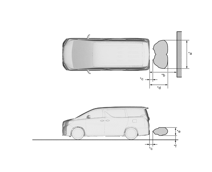
*a Approximately 1600 mm (63.0 in.) *b Approximately 1500 mm (59.1 in.) *c Approximately 200 mm (7.87 in.) *d Approximately 1150 mm (45.3 in.) *e Approximately 500 mm (19.7 in.) *f Approximately 225 mm (8.86 in.) Detection Area - -
-
-
-
DIAGNOSIS
-
If a system malfunction is detected, the clearance warning ECU assembly stores Diagnostic Trouble Codes (DTCs) in its memory. For details, refer to the Repair Manual.
-