MONITOR SYSTEM
-
FUNCTION OF MAIN COMPONENTS
Component Function Rear Television Camera Assembly Transmits a video signal of the area behind the vehicle to the radio and display receiver assembly. Radio and Display Receiver Assembly
-
Receives signals from the BACK UP LP relay and turns the rear television camera assembly on and off.
-
Displays the image transmitted by the rear television camera assembly on the screen.
Park/Neutral Position Switch Assembly Sends an R shift position signal to the radio and display receiver assembly. -
-
SYSTEM CONTROL
-
This system operates when both the following conditions have been met:
-
Engine switch on (IG).
-
Reverse (R) is selected.
-
-
-
FUNCTION
-
Area Displayed on Screen
-
Objects on the right of the vehicle appear on the right side of the display panel, and objects on the left of the vehicle appear on the left side of the display panel.
-
The rear television camera assembly uses a wide-angle lens. The perceived distance from images that appear on the screen differs from the actual distance.
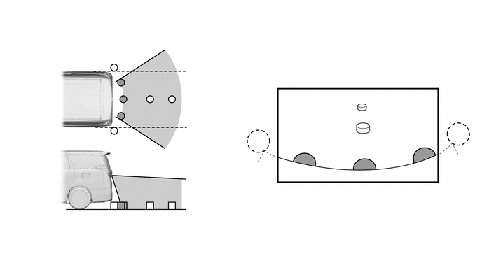
Note
The area displayed on the screen may vary according to vehicle status or road conditions. The area covered by the rear television camera assembly is limited. The rear television camera assembly does not show objects close to either corner of the bumper or show the area under the bumper.
-
-
-
FAIL-SAFE
-
The table below indicates fail-safe operation when a malfunction is detected:
Malfunctioning Part Detection Item Function Rear Television Camera Assembly Rear television camera assembly malfunction signal is detected. System stops signal reception and displays a dark screen.
-