REAR SUSPENSION SYSTEM
-
CONSTRUCTION
-
High tensile strength pressed sheet steel is used for the rear trailing arm assembly, rear upper control arm assembly, rear No. 1 suspension arm assembly and rear No. 2 suspension arm assembly, achieving both weight reduction and structural rigidity.
-
A forked rear No. 1 suspension arm assembly is used. The angle of the shock absorber has been optimized so that it sits between the forks to accommodate the low floor design.
-
The rear No. 2 suspension arm assembly has a pressed and welded sheet steel construction, achieving a compact and rigid design.
-
The rear upper control arm assembly has a welded T-shape construction, achieving a reduction in weight and good structural rigidity.
-
A protruding shaped inner tube bush is used in the rear upper control arm assembly, rear No. 1 suspension arm assembly and rear No. 2 suspension arm assembly, reducing the torsion stiffness of the bush while maintaining lateral rigidity, ensuring decreased road noise and excellent suspension response.
-
The size of the axial holes in the trailing arm bush are optimized to reduce shock generated while driving on an uneven road surface.
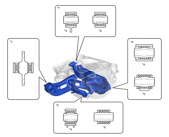
*a Vehicle Body Side *b Axle Side *c Cross Section of Rear Trailing Arm Assembly Mounting *d Cross Section of Rear No. 1 Suspension Arm Assembly Mounting *e Cross Section of Rear No. 2 Suspension Arm Assembly Mounting *f Cross Section of Rear Upper Control Arm Assembly Mounting -
Rear suspension arm covers are attached to the rear No. 1 suspension arm assembly and rear No. 2 suspension arm assembly to control airflow under the floor of the vehicle, contributing to excellent fuel efficiency and vehicle controllability.
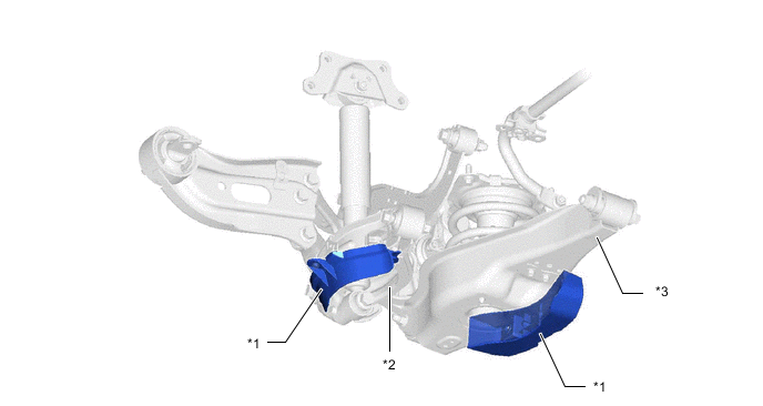
*1 Rear Suspension Arm Cover *2 Rear No. 1 Suspension Arm Assembly *3 Rear No. 2 Suspension Arm Assembly - -
-