BRAKE CONTROL SYSTEM
-
OPERATION
-
Engine Output Control during TRC or VSC Operation
-
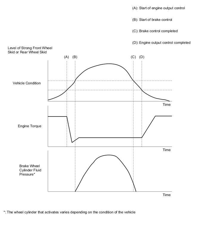
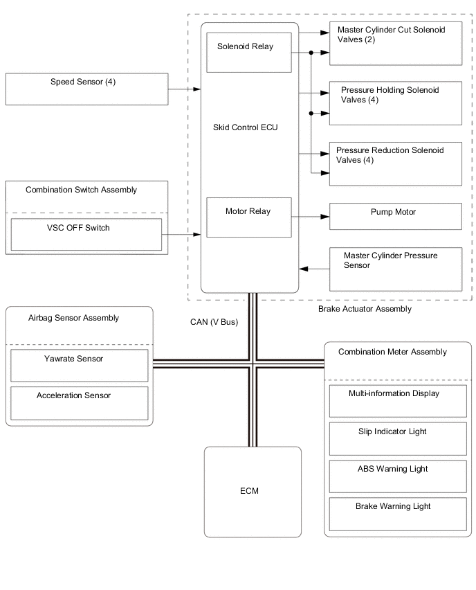
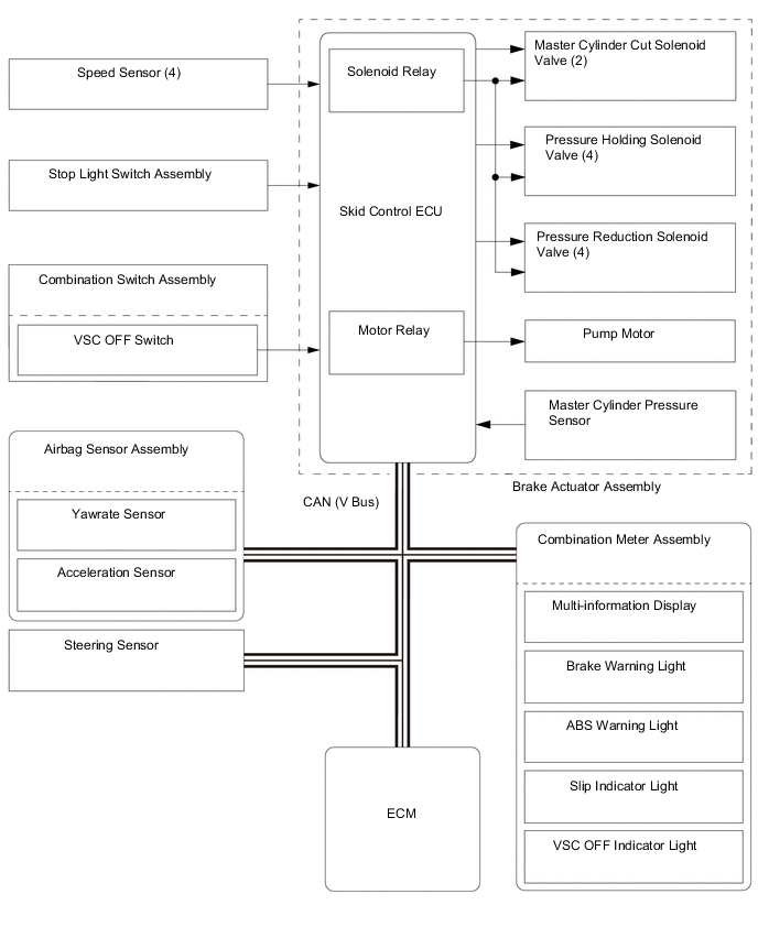
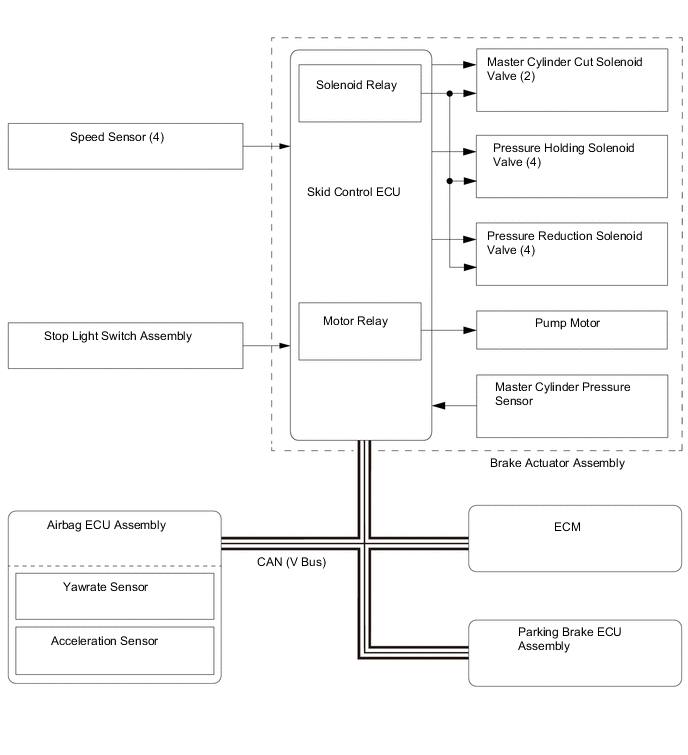
During the TRC or VSC operation, the skid control ECU outputs the engine output control signal to the ECM. Upon receiving this signal, the ECM inhibits the engine output.
-
-
ABS and EBD
-
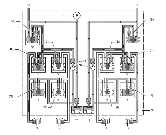
Based on the signals received from the 4 speed sensors, the skid control ECU calculates the speed of each wheel and checks the wheel slipping conditions. In accordance with the slipping condition, the skid control ECU controls each solenoid valve in the brake actuator assembly in order to adjust the fluid pressure of each wheel cylinder in the following 3 modes: pressure increase, pressure holding and pressure reduction modes.
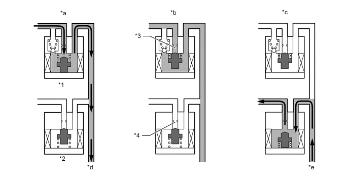
*1 Pressure Holding Solenoid Valve *2 Pressure Reduction Solenoid Valve *3 Port A *4 Port B *a Pressure Increase Mode *b Pressure Holding Mode *c Pressure Reduction Mode *d To Brake Caliper *e From Brake Caliper - - Brake Actuator Operation in ABS and EBD Pressure Mode Increase Mode Holding Mode Reduction Mode Pressure Holding Solenoid Valve (Port A) Off (Open) On (Closed) ← Pressure Reduction Solenoid Valve (Port B) Off (Closed) ← On (Open) Wheel Cylinder Pressure Increases Holds Reduces
-
-
Brake Assist
-
In the event of emergency braking, the skid control ECU determines the driver's intention based on the speed of the pressure increase in the master cylinder determined by the master cylinder pressure sensor signal. If the skid control ECU judges the need for additional brake assist, pressure is generated by the pump in the brake actuator and directed to the wheel cylinder to apply a large amount of fluid pressure.
-
When the vehicle is fully loaded, based on the master cylinder pressure sensor signal, the skid control ECU may provide brake assist other than when emergency braking.
-
In certain situations when the vacuum pressure of the vacuum booster calculated using the vacuum booster pressure sensor and atmospheric pressure sensor is low, based on the master cylinder pressure sensor signal, the skid control ECU may provide brake assist.*
*: Models for 2AR-FE engine
-
In the event of a brake booster failure, based on the brake pedal load sensing switch and master cylinder pressure sensor signals, the skid control ECU may provide brake assist.
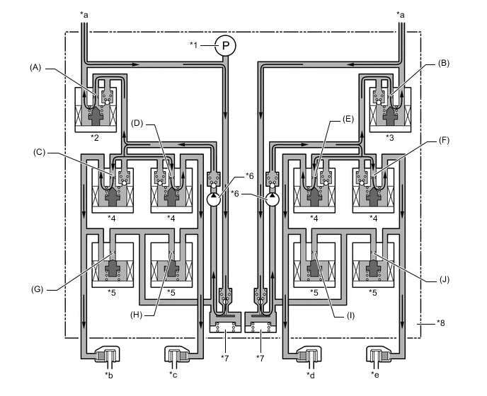
*1 Master Cylinder Pressure Sensor *2 No. 1 Master Cylinder Cut Solenoid Valve *3 No. 2 Master Cylinder Cut Solenoid Valve *4 Pressure Holding Solenoid Valve *5 Pressure Reduction Solenoid Valve *6 Pump *7 Reservoir *8 Brake Actuator *a From Brake Master Cylinder Sub-assembly *b Front Brake Caliper RH *c Rear Brake Caliper LH *d Rear Brake Caliper RH *e Front Brake Caliper LH - - Brake Actuator Operation in Brake Assist Item Brake Assist Not Activated Brake Assist Activated Pump Off On No. 1 Master Cylinder Cut Solenoid Valve Port (A) Off (Open) On* No. 2 Master Cylinder Cut Solenoid Valve Port (B) Off (Open) On* Pressure Holding Solenoid Valve Port (C) Off (Open) ← Port (D) Off (Open) ← Port (E) Off (Open) ← Port (F) Off (Open) ← Pressure Reduction Solenoid Valve Port (G) Off (Closed) ← Port (H) Off (Closed) ← Port (I) Off (Closed) ← Port (J) Off (Closed) ← Tech Tips
*: The solenoid valve switches the hydraulic pressure between "open" and "closed" in accordance with the operating conditions by adjusting continually.
-
-
Traction Control (TRC)
-
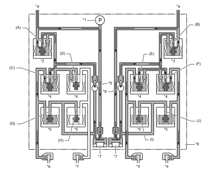
The fluid pressure generated by the pump is regulated by the master cylinder cut solenoid valve to the required pressure. Thus, the wheel cylinders of the drive wheels are controlled in the following 3 modes: pressure increase, pressure holding, and pressure reduction modes to control the slippage of the drive wheels. The pressure holding solenoid valve and the pressure reduction solenoid valve are turned on or off in accordance with the ABS and EBD operation patterns.
*1 Master Cylinder Pressure Sensor *2 No. 1 Master Cylinder Cut Solenoid Valve *3 No. 2 Master Cylinder Cut Solenoid Valve *4 Pressure Holding Solenoid Valve *5 Pressure Reduction Solenoid Valve *6 Pump *7 Reservoir *8 Brake Actuator *a From Brake Master Cylinder Sub-assembly *b Front Brake Caliper RH *c Rear Brake Caliper LH *d Rear Brake Caliper RH *e Front Brake Caliper LH - - Brake Actuator Operation in TRC Item TRC Operation Not Activated Pressure Increase Mode Pressure Holding Mode Pressure Reduction Mode Pump Off On ← ← No. 1 Master Cylinder Cut Solenoid Valve Port (A) Off (Open) On* ← ← No. 2 Master Cylinder Cut Solenoid Valve Port (B) Off (Open) On* ← ← Front Brake Pressure Holding Solenoid Valve Port (C) Off (Open) ← On (Closed) ← Port (F) Off (Open) ← On (Closed) ← Pressure Reduction Solenoid Valve Port (G) Off (Closed) ← ← On (Open) Port (J) Off (Closed) ← ← On (Open) Rear Brake Pressure Holding Solenoid Valve Port (D) Off (Open) On (Closed) ← ← Port (E) Off (Open) On (Closed) ← ← Pressure Reduction Solenoid Valve Port (H) Off (Closed) ← ← ← Port (I) Off (Closed) ← ← ← Tech Tips
*: The solenoid valve switches the hydraulic pressure between "open" and "closed" in accordance with the operating conditions by adjusting continually.
-
-
Vehicle Stability Control (VSC)
-
The VSC, by the way of solenoid valves, controls fluid pressure generated by the pump and applies it to the brake wheel cylinder of each wheel in the following 3 modes: pressure increase, pressure holding, and pressure reduction modes. As a result, the tendency of front wheel skid or rear wheel skid is controlled.
-
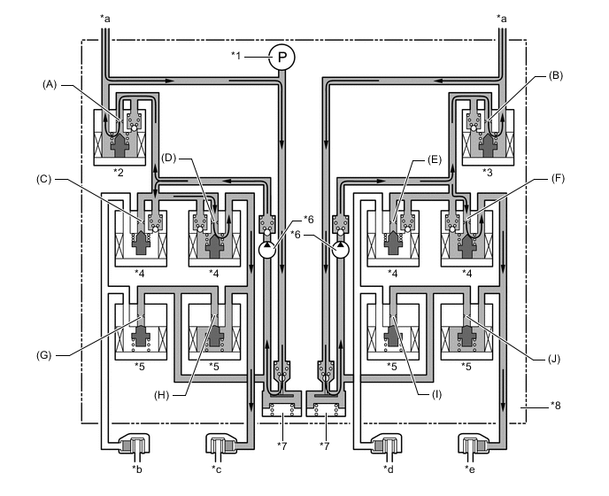
In the front wheel skid restraining control, the brakes of the front wheels and rear wheel of the inner circle of the turn are applied. Also, depending on whether the brake is on or off and also depending on the condition of the vehicle, there are circumstances in which the brake might not be applied to the wheels even if the wheel is targeted for braking. The following diagram shows the hydraulic circuit in pressure increase mode, as it controls a front wheel skid condition while the vehicle is making a right turn. In other operating modes, the pressure holding valve and the pressure reduction valve are turned on or off in accordance with the ABS and EBD operation patterns.
*1 Master Cylinder Pressure Sensor *2 No. 1 Master Cylinder Cut Solenoid Valve *3 No. 2 Master Cylinder Cut Solenoid Valve *4 Pressure Holding Solenoid Valve *5 Pressure Reduction Solenoid Valve *6 Pump *7 Reservoir *8 Brake Actuator *a From Brake Master Cylinder Sub-assembly *b Front Brake Caliper RH *c Rear Brake Caliper LH *d Rear Brake Caliper RH *e Front Brake Caliper LH - - Brake Actuator Operation in VSC (Front Wheel Skid Restraining) Item VSC Operation Not Activated Pressure Increase Mode Pressure Holding Mode Pressure Reduction Mode Pump Off On ← ← No. 1 Master Cylinder Cut Solenoid Valve Port (A) Off (Open) On* ← ← No. 2 Master Cylinder Cut Solenoid Valve Port (B) Off (Open) On* ← ← Front Brake Pressure Holding Solenoid Valve Port (C) Off (Open) ← On (Closed) ← Port (F) Off (Open) ← On (Closed) ← Pressure Reduction Solenoid Valve Port (G) Off (Closed) ← ← On (Open) Port (J) Off (Closed) ← ← On (Open) Rear Brake Pressure Holding Solenoid Valve Port (D) Off (Open) On (Closed) ← ← Port (E) Off (Open) ← On (Closed) ← Pressure Reduction Solenoid Valve Port (H) Off (Closed) ← ← ← Port (I) Off (Closed) ← ← On (Open) Tech Tips
*: The solenoid valve switches the hydraulic pressure between "open" and "closed" in accordance with the operating conditions by adjusting continually.
-
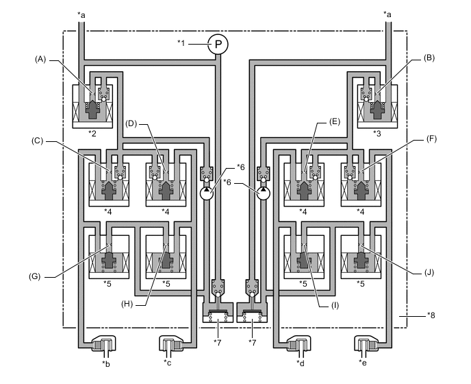
During the rear wheel skid restraining control, the brakes of the front and rear wheels on the outer circle of the turn are applied. Also, depending on whether the brake is on or off and also depending on the condition of the vehicle, there are circumstances in which the brake might not be applied to the wheels even if the wheel is targeted for braking. The following diagram shows the hydraulic circuit in pressure increase mode, as it controls a rear wheel skid condition while the vehicle is making a right turn. In other operating modes, the pressure holding valve and the pressure reduction valve are turned on or off in accordance with the ABS and EBD operation patterns.
*1 Master Cylinder Pressure Sensor *2 No. 1 Master Cylinder Cut Solenoid Valve *3 No. 2 Master Cylinder Cut Solenoid Valve *4 Pressure Holding Solenoid Valve *5 Pressure Reduction Solenoid Valve *6 Pump *7 Reservoir *8 Brake Actuator *a From Brake Master Cylinder Sub-assembly *b Front Brake Caliper RH *c Rear Brake Caliper LH *d Rear Brake Caliper RH *e Front Brake Caliper LH - - Brake Actuator Operation in VSC (Rear Wheel Skid Restraining) Item VSC Operation Not Activated Pressure Increase Mode Pressure Holding Mode Pressure Reduction Mode Pump Off On ← ← No. 1 Master Cylinder Cut Solenoid Valve Port (A) Off (Open) On* ← ← No. 2 Master Cylinder Cut Solenoid Valve Port (B) Off (Open) On* ← ← Front Brake Pressure Holding Solenoid Valve Port (C) Off (Open) On (Closed) ← ← Port (F) Off (Open) ← On (Closed) ← Pressure Reduction Solenoid Valve Port (G) Off (Closed) ← ← ← Port (J) Off (Closed) ← ← On (Open) Rear Brake Pressure Holding Solenoid Valve Port (D) Off (Open) ← On (Closed) ← Port (E) Off (Open) On (Closed) ← ← Pressure Reduction Solenoid Valve Port (H) Off (Closed) ← ← On (Open) Port (I) Off (Closed) ← ← ← Tech Tips
*: The solenoid valve switches the hydraulic pressure between "open" and "closed" in accordance with the operating conditions by adjusting continually.
-
-
Hill-start Assist Control
-
Hill-start assist control operation is performed by closing the master cylinder cut solenoid valves after the driver operates the brake pedal and leaving a certain amount of hydraulic pressure generated by the pump in the wheel cylinder. The diagram below shows the hydraulic circuit in the pressure holding mode.
*1 Master Cylinder Pressure Sensor *2 No. 1 Master Cylinder Cut Solenoid Valve *3 No. 2 Master Cylinder Cut Solenoid Valve *4 Pressure Holding Solenoid Valve *5 Pressure Reduction Solenoid Valve *6 Pump *7 Reservoir *8 Brake Actuator *a From Brake Master Cylinder Sub-assembly *b Front Brake Caliper RH *c Rear Brake Caliper LH *d Rear Brake Caliper RH *e Front Brake Caliper LH - - Brake Actuator Operation in Hill-start Assist Control and Brake Hold Item Hill-start Assist Control and Brake Hold Operation Not Activated Pressure Holding Mode Pressure Reduction Mode No. 1 Master Cylinder Cut Solenoid Valve Port (A) Off (Open) On (Closed) Off (Open) No. 2 Master Cylinder Cut Solenoid Valve Port (B) Off (Open) On (Closed) Off (Open) Front Brake Pressure Holding Solenoid Valve Port (C) Off (Open) ← ← Port (F) Off (Open) ← ← Pressure Reduction Solenoid Valve Port (G) Off (Closed) ← ← Port (J) Off (Closed) ← ← Rear Brake Pressure Holding Solenoid Valve Port (D) Off (Open) ← ← Port (E) Off (Open) ← ← Pressure Reduction Solenoid Valve Port (H) Off (Closed) ← ← Port (I) Off (Closed) ← ←
-
-
Steering Cooperative Control
-
The operation of the solenoid valves under the steering cooperative control is the same as the TRC or VSC operation.
-
-
Brake Hold
-
The operation of the solenoid valves under the brake hold is the same as the operation of the hill-start assist control.
-
-