BODY STRUCTURE
-
FUNCTION
-
Front Wheel Opening Extension Pad
-
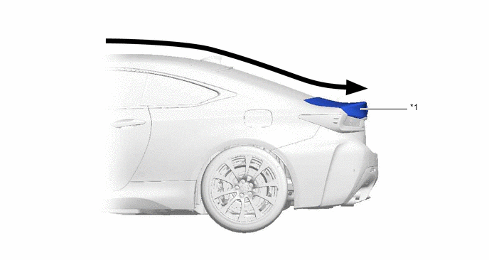
A front wheel opening extension pad is used to reduce the volume of air hitting against the rotating body of the tire. As a result, turbulence generated by the rotation of the front tire which disturbs the surrounding airflow has been suppressed, thus reducing air resistance and ensuring a high level of straight-line stability at high speed.
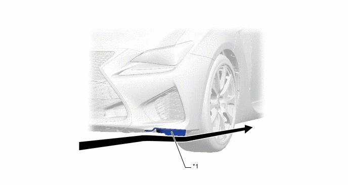
*1 Front Wheel Opening Extension Pad - - 
Airflow - -
-
-
Front Fender Liner
-
A groove is provided in the front fender liner. As a result, air in the wheelhouse flows parallel to the tires and ensures smooth airflow through the wheelhouse, thus ensuring superior stability.
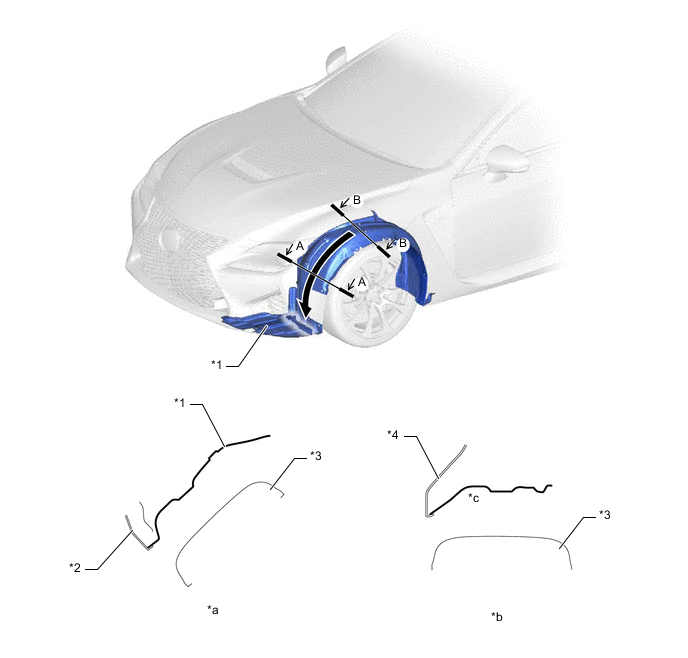
*1 Front Fender Liner *2 Front Bumper Cover *3 Front Tire *4 Front Fender Panel *a A-A Cross Section *b B-B Cross Section *c Groove Structure - - Airflow - -
-
-
Rear Floor Housing Shield
-
A rear floor housing shield is used to reduce the volume of air hitting against the rotating body of the tire. As a result, turbulence generated by the rotation of the rear tire which disturbs the surrounding airflow has been suppressed, thus reducing air resistance and ensuring a high level of straight-line stability at high speed.
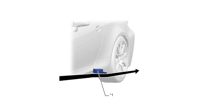
*1 Rear Floor Housing Shield - - Airflow - -
-
-
Rear Wheel House Liner
-
Ridges are provided to direct high-pressure turbulence in the rear wheelhouse caused by the rotation of the rear tire out from the vehicle.
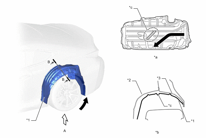
*1 Rear Wheel House Liner *2 Inner Quarter Wheel House Panel *3 Outer Quarter Wheel House Panel - - *a View from A *b B-B Cross Section *c Ridge - - Airflow - -
-
-
Luggage Compartment Door
-
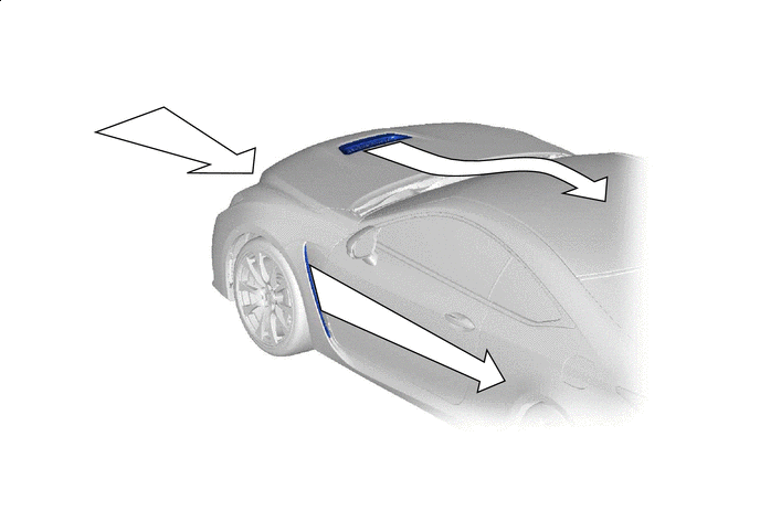
The rear end portion of the luggage compartment door panel sub-assembly has been given a sharp edge to smoothly introduce airflow from the roof to the rear.
*1 Luggage Compartment Door Panel Sub-assembly - - Airflow - -
-
-
Aero Stabilizing Fin
-
Aero stabilizing fins are provided on the front pillar and on each rear combination light lens for enhanced aerodynamics.
-
After passing the aero stabilizing fin, the air speed will increase and a vortex will be generated.
-
This vortex increases the speed of the surrounding air while at the same time pulling the airflow towards the vehicle body.
-
The airflow with higher speed passes near both sides of the vehicle body and ends at the rear of the vehicle. This helps to hold the vehicle body, thus stabilizing the vehicle.
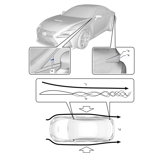
*a Aero Stabilizing Fin *b Vortex generated at the rear of the aero stabilizing fin *c Surrounding air increases speed and is pushed against the body *d Vehicle stability is achieved due to the body held by airflow Airflow 
Holds the Vehicle from Both Sides
-
-
-
Under Body
-
Smooth airflow under the floor of the vehicle of the vehicle enhances the speed of airflow and creates a low pressure region between the vehicle and the road surface (Venturi effect). This low pressure region attracts the vehicle to the road surface, thus causing down force. As a result, superior straight-line stability has been achieved. To create a smooth rearward airflow under the vehicle, the following parts located on the underside of the vehicle are designed to alter the airflow.
-
A flat airflow adjustment surface is provided for the No. 1 engine under cover assembly. Also, an aero stabilizing fin is provided.
-
The surface area of the front floor cover and the front floor center cover has been increased, and the height from the ground has also been optimized. In addition, an aero stabilizing fin is provided.
-
The under floor cutting angle of the No. 1 floor under cover assembly has been optimized. In addition, an aero stabilizing fin is provided.
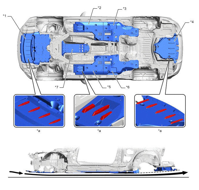
*1 No. 1 Engine Under Cover Assembly *2 Front Floor Cover LH *3 Front Floor Center Cover LH *4 No. 1 Floor Under Cover Assembly *5 Front Floor Cover RH *6 Front Floor Center Cover RH *7 No. 2 Engine Under Cover Assembly - - *a Aero Stabilizing Fin - - Airflow - - -
-
-
Air Outlet
-
Openings have been provided on the hood and fenders to allow air to exit smoothly from the engine compartment thus ensuring superior maneuvering stability.
Airflow - - -
-