METER / GAUGE SYSTEM
-
FUNCTION
-
Multi Buzzer
-
The table below shows the warning and reminder functions of the buzzer in the combination meter assembly.
Priority Item 1 Engine Start while Driving Notice 2 Engine Switch Operation while Driving Warning 3 Front Seat Belt Warning (Level 2) 4 Rear Seat Belt Warning*1 5 Front Seat Belt Warning (Level 1) 6 Unexpected Vehicle Motion Warning 7 Brake Fluid Low Warning 8 Engine Oil Pressure Warning 9 EPS Warning 10 Lane Departure Alert Warning*2 11 Engine Coolant Temperature Warning 12 Door Open when Shift Lever not in P Warning 13 Entry and Start System Warning 1 (Intermittent) 14 Entry and Start System Warning 2 (Intermittent) 15 Entry and Start System Warning (Once) 16 Multi-information Display Warning 17 Dynamic Radar Cruise Control Cancelation due to Low Speed Warning*3 18 Immobiliser Certification Reminder 19 Speed Limit Exceed Warning*4 20 Parking Brake Engaged Warning 21 Door Open while Driving Warning 22 Sport Shift Reject Warning 23 Light Reminder*5 24 Rev Indicator 25 Turn Signal/Hazard Warning Operation *1: Models with rear seat belt warning function
*2: Models with lane departure alert system
*3: Models with dynamic radar cruise control system
*4: Models for G.C.C. countries
*5: Models for Europe and destination package for South Africa
-
-
Multi-information Display
-
Display Function Flow
-
The multi-information display can be switched as shown in the flow chart below:
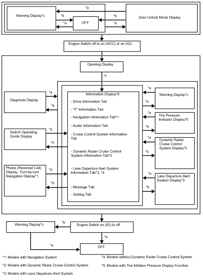
Item Display Change Condition *a Conditions are not met. *b Conditions are met. *c If there are multiple display requests, items will be displayed in sequence. *d An item or display is selected by operating the steering pad switch assembly. *e ODO display is displayed for a certain period of time after the engine switch is turned off. *f After engine switch on (IG).
-
-
Display Tab Operation
-
The information currently displayed can be switched using the RIGHT/LEFT switch of the steering pad switch assembly.
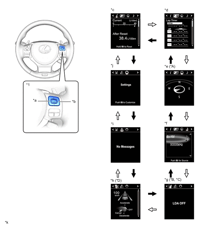
*A Models with Navigation System *B Models with Lane Departure Alert System *C Models without Dynamic Radar Cruise Control System *D Models with Dynamic Radar Cruise Control System *1 Steering Pad Switch Assembly - - *a LEFT Switch *b RIGHT Switch *c Drive Information *d "F" Information *e Navigation Information *f Audio Information *g Lane Departure Alert System Information *h Dynamic Radar Cruise Control System Information *i Message *j Settings *k The illustrations shown are examples only. - - 
RIGHT switch operation 
LEFT switch operation
-
-
Drive Information
-
The drive information tab shows vehicle information such as drivable range and fuel consumption.
-
The drive information display can be changed using the UP/DOWN switch of the steering pad switch assembly.
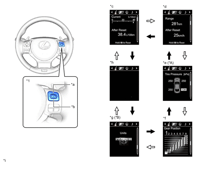
*A Models with Tire Inflation Pressure Display Function *B Destination Package for United Kingdom *1 Steering Pad Switch Assembly - - *a UP Switch *b DOWN Switch *c Drive Information 1 *d Drive Information 2 *e Tire Pressure Indicator *f Gear Position Indicator *g Unit Change *h Blank *i The illustrations shown are examples only. - - DOWN switch operation UP switch operation
-
-
"F" Information
-
The "F" information tab shows vehicle information such as G-force and rear wing position.
-
The "F" information currently displayed can be changed using the UP/DOWN switch of the steering pad switch assembly.
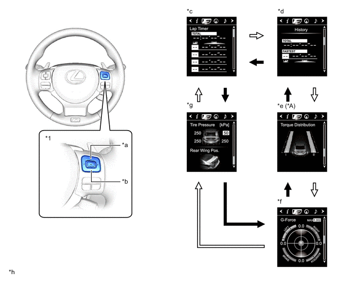
*A Models with Torque Vectoring Differential - - *1 Steering Pad Switch Assembly - - *a UP Switch *b DOWN Switch *c Lap Timer *d Lap Time History *e Torque Distribution *f G-force *g Vehicle Monitor *h The illustrations shown are examples only. DOWN switch operation UP switch operation
-
-
Setting Function
-
The items displayed on the multi-information display can be customized.
-
The following items can be selected on the information setting screen.
Item Available Setting Language
-
The language used on the multi-information display can be selected:
-
English
-
French
-
Spanish
-
German*1
-
Italian*1
-
Russian*1
-
Chinese*2
Unit
-
The unit displayed on the multi-information display can be selected:
-
miles (MPG) (Default*3)
-
km (km/L) (Default*4)
-
km (L/100 km) (Default*5)
Eco Driving Indicator Light
-
The Eco Driving Indicator Light can be switched:
-
ON (Default)
-
OFF
TOP Switch Settings
-
The item that is displayed when the TOP switch is pressed can be selected among the following:
-
Drive Information 1 (Default)
-
Drive Information 2
-
Lap Timer
-
Lap Time History
-
Torque Distribution*6
-
G-force
-
Vehicle Monitor
-
Tire Pressure Indicator*7
-
Gear Position Indicator
-
Unit Change*3
-
Navigation Information*8
-
Audio Information
-
Cruise Control System Information
-
Dynamic Radar Cruise Control System Information*9
-
Lane Departure Alert System Information*10, *11
-
Message
-
Settings
-
Blank
Drive Information 1
-
2 items can be selected among the following:
-
Current Fuel Consumption (Bar Display)/Average Fuel Consumption (Mark Display) (Default of upper area)
-
Total Average Fuel Consumption Between Reset Operations (Default of lower area)
-
Average Fuel Consumption After Engine Start-up
-
Average Fuel Consumption After Refueling
-
Total Average Vehicle Speed Between Reset Operations
-
Average Vehicle Speed After Engine Start-up
-
Total Elapsed Time Between Reset Operations
-
Elapsed Time After Engine Start-up
-
Cruising Range
-
Cruising Range After Engine Start-up
-
Blank
Drive Information 2
-
2 items can be selected among the following:
-
Current Fuel Consumption (Bar Display)/Average Fuel Consumption (Mark Display)
-
Total Average Fuel Consumption Between Reset Operations
-
Average Fuel Consumption After Engine Start-up
-
Average Fuel Consumption After Refueling
-
Total Average Vehicle Speed Between Reset Operations (Default of lower area)
-
Average Vehicle Speed After Engine Start-up
-
Total Elapsed Time Between Reset Operations
-
Elapsed Time After Engine Start-up
-
Cruising Range (Default of upper area)
-
Cruising Range After Engine Start-up
-
Blank
Interruption Display
-
The following displays that appear as soon as the set conditions are met can be switched to ON (Default) or OFF:
-
Turn-by-turn Navigation Display*8
-
Incoming Telephone Display
-
Dynamic Radar Cruise Control Switch Operation Guide*9
-
Rheostat
-
TVD Mode*6
-
Drive Mode
Rev Indicator
-
The rev indicator can be switched:
-
ON (Default)
-
OFF
-
The rev indicator setting can be selected when the rev indicator is ON:
-
Setting 1 (fast timing)
-
Setting 2 (middle timing) (Default)
-
Setting 3 (slow timing)
Tachometer Peak Hold Function
-
The tachometer peak hold function can be switched:
-
ON (Default)
-
OFF
Vehicle Speed Warning*12
-
The vehicle speed warning can be switched:
-
ON
-
OFF (Default)
Tech Tips
-
The vehicle speed for warning activation can be set at increments of 1 km/h or 1 mph between 50 and 120 km/h*13 or 50 and 160 km/h (30 and 100 mph)*3 or 50 and 200 km/h*5.
-
The maximum value varies according to the countries and regions.
Rear Wing
-
The active rear wing function can be switched:
-
ON
-
OFF (Default)
Sport Screen
-
The SPORT S mode display can be changed:
-
White ribbon type tachometer (Default)
-
Digital type tachometer
-
The SPORT S+ mode display can be changed:
-
White ribbon type tachometer
-
Digital type tachometer (Default)
Initialization The set items can be initialized. *1: Models for Europe
*2: Except models for Europe
*3: Destination package for United Kingdom
*4: Destination package for South Korea
*5: Models and destination packages for other countries
*6: Models with torque vectoring differential
*7: Models with tire inflation pressure display function
*8: Models with navigation system
*9: Models with dynamic radar cruise control system
*10: Models with lane departure alert system
*11: Models without dynamic radar cruise control system
*12: Except models for G.C.C. countries
*13: Models for China and destination packages for Brunei, Indonesia, Taiwan, Philippines and South Korea
-
-
-
Warning Mode Function
-
When a warning is necessary, the warning display interrupts the current display on the multi-information display.
-
The master warning light may illuminate or blink and the buzzer in the combination meter assembly may sound depending on the item displayed on the multi-information display.
Priority Display Master Warning Light Buzzer 1 TVD Test Mode*1 - - Adjusting LDA Camera*2 - - Adjusting Front Radar Beam*3, *4 - - Checking Cruise Control C/D*3 - - Checking Cruise Control Brake*3 - - BRAKE!*4 - -*5 Holding in Engine Switch Will Cause an Emergency Engine Stop. Blinks Sounds To Restart Car, Shift Lever to "N" and Press Engine Switch. Blinks Sounds The Engine Has Stopped. Please Put Shift Lever into "P". Blinks Sounds The Engine Has Stopped. Please Stop Your Car in a Safe Place. Blinks Sounds 2 Dynamic radar cruise control warning reminder indicator (image display)*3 - - Lane departure alert warning reminder indicator (image display)*2 - - Brake Malfunction Blinks Sounds The Accelerator is Stuck. Please Depress Brake Pedal to Stop Car. Blinks Sounds 3 Door open (while driving)*6 Blinks Sounds Door open - - Clearance sonar detection (image display)*7 - - Check Park Sonar System*7 Illuminates - Clean Park Sonar*7 Illuminates - 4 Auto Power OFF to Conserve Battery - - 5 Shift to P position when parked Blinks Sounds EPS Failure. Steering Wheel Harder to Turn. Illuminates Sounds Voltage Abnormality. Steering Wheel Harder to Turn. Illuminates Sounds Check Power Steering System Illuminates Sounds Release Parking Brake Blinks Sounds Key not detected Blinks Sounds 6 1st Gear not available due to slippery road surface Illuminates Sounds Speed Limit Exceeded*8 Blinks Sounds 7 Check SRS Airbag System Illuminates Sounds Check ABS - Sounds Engine Coolant High Temperature Illuminates Sounds Clean Radar Sensor*3, *4 Illuminates Sounds Cruise Control not available*3 Illuminates Sounds LDA not available*2 Illuminates Sounds Check Entry & Start System Blinks Sounds BSM not available*9 Illuminates Sounds Check Cruise Control System*3 Illuminates Sounds Check LDA System*2 Illuminates Sounds Check PCS System*4 Illuminates Sounds Check BSM System*9 Illuminates Sounds Engine Oil Pressure Low Illuminates Sounds Transmission Fluid High Temperature Illuminates Sounds LDA System is Unavailable Below Approx. 50 km/h.*2 - - LDA System is Unavailable Below Approx. 32 MPH.*2 - - LDA System is Unavailable at this Speed.*2 - - 8 Dynamic radar cruise control indicator (image display)*3 - - Lane departure alert indicator (image display)*2 - - Engine Stopped, Steering Wheel Harder to Turn. Illuminates Sounds Turn Power OFF Blinks Sounds Key detected in vehicle Blinks Sounds Turn Light Off Blinks Sounds Moon Roof opened*10 Blinks Sounds Window opened Blinks Sounds Window/Moon Roof opened*10 Blinks Sounds Depress brake pedal, touch engine switch with key Blinks Sounds Depress brake pedal and push engine switch to start - - Depress brake pedal and push engine switch to start - Sounds The Accelerator is Stuck. Please Check the Accelerator. Blinks Sounds 9 Steering Lock active Blinks Sounds TVD System Malfunction. Visit Your Dealer.*1 Illuminates Sounds TVD System Overheated. Reduce Engine Speed and Load.*1 Illuminates Sounds Brake Override System Failure. Illuminates Sounds 10 Key Battery Low Illuminates Sounds Engine Oil Level Low Illuminates Sounds Check Headlight System Illuminates Sounds Brake Pad Wear. Visit Your Dealer. Illuminates Sounds Both Accelerator and Brake Pedals Are Depressed. Blinks - Tire pressure indicator (image display)*11 - - 11 Active Rear Wing Malfunction. Visit Your Dealer. Illuminates Sounds Washer Fluid Low - - Fuel Low - - Injector Maintenance required soon*12 Illuminates - Injector Maintenance required*12 Illuminates - Turn on the high beam to activate AHB System*13 - - Depress brake pedal and push engine switch to start - - VSC System Switched Off. Pre-Crash Brake System Disengaged.*4 - - PCS temporarily not available*4 - - Operation of Electrical Items Restricted. - - Theft Sensor OFF - - Theft Sensor ON - - *1: Models with torque vectoring differential
*2: Models with lane departure alert system
*3: Models with dynamic radar cruise control system
*4: Models with pre-crash safety system
*5: Skid control buzzer operation is activated.
*6: If the vehicle has reached a speed of 5 km/h (3 mph)
*7: Models with LEXUS parking assist-sensor system
*8: Models for G.C.C. countries
*9: Models with blind spot monitor system
*10: Models with sliding roof system
*11: Models with tire inflation pressure display function
*12: Models with injector maintenance required reminder function
*13: Models with automatic high beam system
-
-
-
-
OPERATION
-
Eco Driving Indicator Light
-
Eco driving indicator light can operate when all of the following conditions are met:
-
The engine switch is on (IG) and the engine is running.
-
The vehicle is being driven with the shift lever in D.
-
NORMAL mode or ECO mode is selected.
-
The shift paddle switch (transmission shift switch assembly) is not operated.
-
The vehicle is at a speed of 130 km/h (81 mph) or below.
-
-
-
Lap Timer Function
-
A lap time can be measured by operating the steering pad switch assembly.
-
The lap time currently being measured and the most recent lap time are displayed on the tachometer, and the total time since the timer was started, each lap time and the fastest lap time are displayed on the multi-information display.
-
While the timer is operating, the multi-information display can be changed to any display of the "F" information tabs. When the timer is stopped, the display will return to the lap timer display.
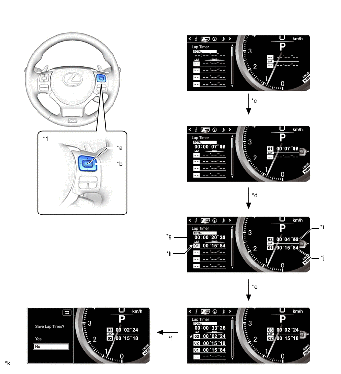
*1 Steering Pad Switch Assembly - - *a ENTER Switch *b RIGHT Switch *c Start (press ENTER switch) *d Lap (press RIGHT switch) *e Stop (press ENTER switch) *f Save (press and hold ENTER switch) *g Total Time *h Fastest Lap Mark *i Current Lap *j Most Recent Lap Time *k The illustrations shown are examples only. - -
-
-
Lap Time History Function
-
The lap time history can be displayed.
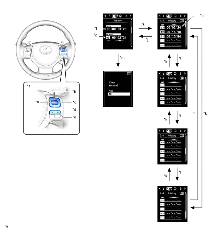
*1 Steering Pad Switch Assembly - - *a ENTER Switch *b UP Switch *c RIGHT Switch *d DOWN Switch *e BACK Switch *f Total Time *g Fastest Lap Time *h Lap Time List *i Press ENTER switch *j Press BACK switch *k Press UP switch *l Press DOWN switch *m Press and hold ENTER switch *n The illustrations shown are examples only.
-
-
Torque Distribution Display Function (Models with Torque Vectoring Differential)
-
The amount of torque distributed to the left and right rear wheels can be displayed.
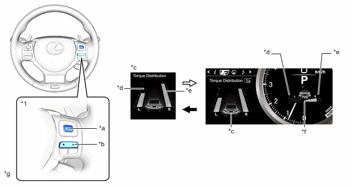
*1 Steering Pad Switch Assembly - - *a ENTER Switch *b BACK Switch *c Torque distribution display on the multi-information display *d Left rear torque amount *e Right rear torque amount *f Torque distribution display on the tachometer *g The illustrations shown are examples only. - - ENTER switch operation BACK switch operation -
On the torque distribution display on the tachometer, the difference between the torque applied to the left and right rear wheels is displayed.
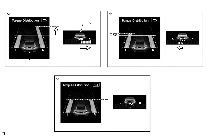
*a Rear right torque is large *b Rear left torque is large *c No difference between rear left and right *d Torque distribution display on the multi-information display *e Torque distribution display on the tachometer *f The illustrations shown are examples only. Difference - - -
A torque peak hold function is provided. If more than 4 segments are illuminated, the maximum segment position is indicated using the yellow frame for 3 seconds.

*a Torque distribution display on the multi-information display *b Torque distribution peak hold display *c The illustration shown is an example only. - -
-
-
G-force
-
Longitudinal and lateral G-force applied to the vehicle can be displayed.
-
By pressing the ENTER switch of the steering pad switch assembly, the G-force is displayed on the tachometer. Additionally, the trace of the maximum G-force is displayed on the multi-information display. This trace can be reset by pressing and holding the ENTER switch.
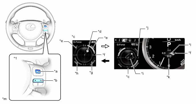
*1 Steering Pad Switch Assembly - - *a ENTER Switch *b BACK Switch *c G-force display on the multi-information display *d G-force of the vehicle *e Steering wheel position *f Current G-force value *g Accelerator pedal input *h Brake fluid pressure *i Record of the maximum G-forces *j Track value of the maximum G-force since display reset *k G-force display on the tachometer *l G-force direction *m The illustration shown is an example only. - - ENTER switch operation BACK switch operation Tech Tips
-
During engine warm-up, steering wheel position, accelerator pedal input and brake fluid pressure are not displayed.
-
This display is intended for use as a guideline. Depending on factors such as the road surface condition, temperature and vehicle speed, the display may not show the actual condition of the vehicle.
-
-
-
Vehicle Monitor
-
The tire pressure indicator* and rear wing position can be displayed.
*: Models with tire inflation pressure display function
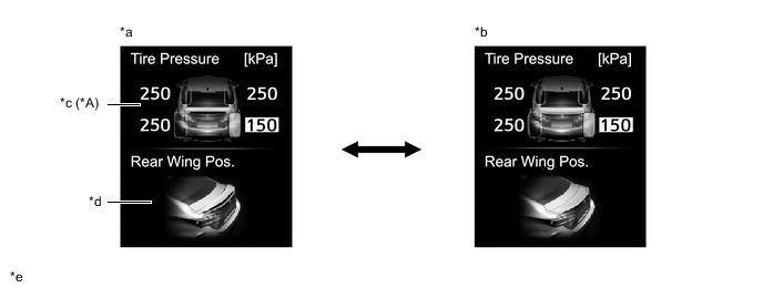
*A Models with Tire Inflation Pressure Display Function - - *a Rear wing raised *b Rear wing retracted *c Tire pressure indicator *d Rear wing position *e The illustrations shown are examples only. - -
-
-