ASC SYSTEM
-
FUNCTION OF MAIN COMPONENTS
Item Function Stereo Component Equalizer Assembly
-
The stereo component equalizer assembly calculates the frequency of the output sound based on the vehicle speed, accelerator pedal depression angle, calculated engine rotation speed, generated torque, shift lever position, shift range and driving mode signals.
-
The stereo component equalizer assembly creates synthesized sounds which are output to the No. 1 speaker with box assembly through the power amplifier.
No. 1 Speaker with Box Assembly Emits sounds based on the signal from the stereo component equalizer assembly. The No. 1 speaker output sound is reverberated in the box. ECM Sends the accelerator pedal depression angle, calculated engine rotation speed, generated torque, shift lever position, shift range and driving mode signals to the stereo component equalizer assembly. Accelerator Pedal Sensor Assembly Sends the accelerator pedal depression angle signal to the ECM. Combination Switch Assembly Sends a drive mode selected signal to the ECM. Skid Control ECU Assembly Detects the signals from each speed sensor and outputs the vehicle speed signal to the ECM. Front RH Speed Sensor Detects the wheel speed of each of the 4 wheels. Front LH Speed Sensor Rear RH Speed Sensor Rear LH Speed Sensor -
-
SYSTEM CONTROL
-
The ASC system uses the stereo component equalizer assembly to generate dynamic engine sounds electronically. These sounds are output from the No. 1 speaker assembly with box. The dynamic engine sounds are calculated in accordance with vehicle information, such as the drive mode, vehicle speed, shift lever position and accelerator pedal opening angle. By operating the vehicle sound switch, the sounds can be turned on/off and volume can be adjusted.
-
The following sounds are generated.
Sound Description Additional Engine Sounds
-
Specially designed engine sounds which are synchronized with the engine speed and output when the vehicle is being driven.
-
Generated when the vehicle speed is 6 km/h (4 mph) or more and engine speed is 980 rpm or more.
Intake Flow Noise
-
Specially designed intake flow noise which is output when the throttle valve is opened rapidly and intake airflow increases.
-
Generated when the engine is running and the accelerator pedal is depressed rapidly.
-
Additional engine sounds generation conditions
Item Condition Remark Drive mode SPORT S+ or CUSTOM* mode - Shift lever position P, R, N, D, M - Vehicle speed 6 km/h (4 mph) or more When all of the conditions are met, additional engine sounds are generated. Engine speed 980 rpm or more *: The additional engine sounds output is performed through the drive mode customization only when POWER mode is selected for the POWER TRAIN item. However, the additional engine sounds output is not performed when NORMAL or ECO mode is selected for the POWER TRAIN item.
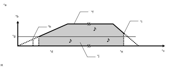
*a Example of additional engine sounds generation *b Vehicle speed *c Time *d Accelerating *e Decelerating *f When vehicle being driven *g 6 km/h (4 mph) *h 980 rpm or more *i Less than 980 rpm *j Sounds output -
Intake flow noise generation conditions
Item Condition Remark Drive mode SPORT S+ mode - Shift lever position P, R, N, D, M - Vehicle speed - - Engine speed Between 1300 rpm and 5000 rpm - Accelerator pedal opening angle Opening angle range:
Between 15% and 70%
Condition:
When the accelerator pedal opening angle increases 15% or more in 0.01 seconds
To generate additional intake flow noise again, decrease the accelerator pedal opening angle to below 10%.
-
-
-
DIAGNOSIS
-
If the stereo component equalizer assembly detects a malfunction in the grille shutter system, Diagnostic Trouble Codes (DTCs) are stored in the stereo component equalizer assembly.
-
The 5-digit DTCs can be read by connecting the Global TechStream (GTS) to the DLC3. For details, refer to the Repair Manual.
-
-