TORQUE VECTORING DIFFERENTIAL SYSTEM
-
CONSTRUCTION
-
An FD21CF Torque Vectoring Differential is available.
-
The FD21CF Torque Vectoring Differential consists of the FD21C type differential and the torque transfer module controlling the amount of torque distributed to the left and right rear wheels.
-
The torque transfer module consists of a torque transfer module motor sub-assembly, motor pinion, temperature sensor, reduction drive gear, reduction driven gear, clutch, planetary gear unit and intermediate shaft.
-
Temperature sensors are installed on the left and right of the torque transfer module. By considering the effect on components as their temperature changes, highly accurate torque transfer is ensured. Additionally, the sensors have a role in preventing malfunctions due to high oil temperatures, enhancing reliability.
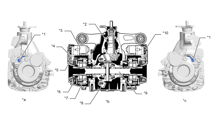
*1 Temperature Sensor *2 Rear Differential Drive Pinion *3 Torque Transfer Module Motor Sub-assembly
-
Motor Rotational Angle Sensor
*4 Reduction Drive Gear *5 Reduction Driven Gear *6 Clutch (Wet Multiple Clutch)
-
Ball Cam
*7 Planetary Gear Unit *8 Ring Gear *9 Intermediate Shaft *10 Motor Pinion *a Left Side View *b Cross Section of Torque Vectoring Differential FDU (Final Drive Unit) *c Right Side View - - -
-
-
OPERATION
-
Transfer of Torque
-
Regulated motor control current is sent from the torque vectoring differential ECU assembly to the torque transfer module motor sub-assembly, rotating the motor pinion.
-
The reduction gear reduces the speed of the motor pinion and transmits the rotation to the ball cam.
-
The ball cam converts rotational force into a linear force which compresses and engages the multiple plate clutch.
-
Engagement of the multiple clutch drives the planetary gear which increases the speed and transmits torque from the differential case to the drive shaft.
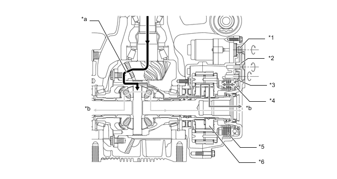
*1 Motor Pinion *2 Reduction Drive Gear *3 Reduction Driven Gear *4 Ball Cam *5 Clutch (Wet Multiple Clutch) *6 Planetary Gear Unit *a Torque Flow *b to Drive Shaft
-
-
Torque Flow
-
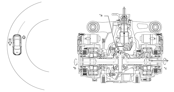
When Traveling Straight
-
When accelerating in a straight line, the torque distribution to the rear wheels is 50:50, similar to a conventional differential.
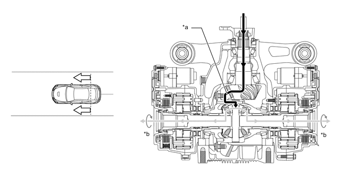
*a Torque Flow *b Drive Torque
-
-
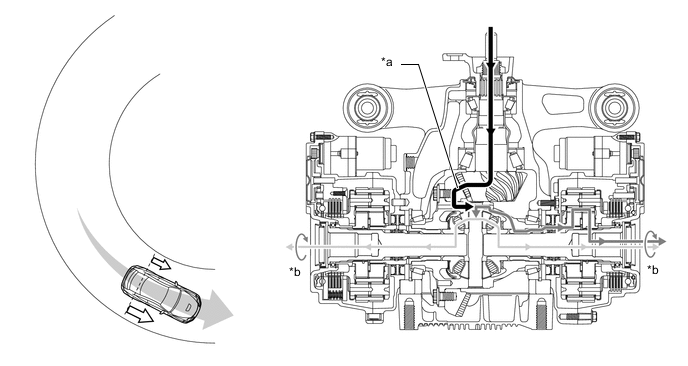
When Entering a Turn and Turning Steadily
-
If no torque is applied to the ring gear or the amount of torque is very small, torque will be generated from the wheel with the most deceleration.
Figure 1. Entering a Turn
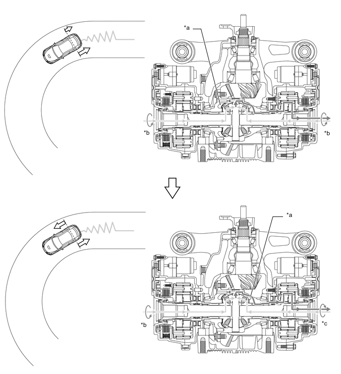
*a Torque Flow *b Coast Torque *c Drive Torque - - Figure 2. Turning Steadily
*a Torque Flow *b Coast Torque *c Drive Torque - -
-
-
Acceleration when Exiting a Turn
-
Torque is transferred to the outer rear wheel of the turn with optimal torque distribution.
*a Torque Flow *b Drive Torque
-
-
-