AIR CONDITIONING SYSTEM
-
CONSTRUCTION
-
Switches for the air conditioning system are located together in the center section of the instrument panel. To operate the air conditioning operation, both the switches located in the air conditioning control assembly and switches displayed on the multi display can be used.
-
In accordance with the adoption of the left and right independent temperature control system, the set temperature switches are provided separately for the driver side and front passenger side. In addition, the DUAL switch is provided to change the mode between cooperated operation mode and left and right independent temperature control mode.
-
A capacitive switch is provided for the temperature setting. Using multiple touch operations, such as a short touch, long touch and sliding touch operation, the temperature setting can be adjusted. The switch detects the voltage changes that occur when the capacitive switch is operated and changes the temperature setting.
-
For blower customization control, the multi-display has the FAST SOFT switch.
Figure 1. Air Conditioning Control Panel Location (LHD Models)
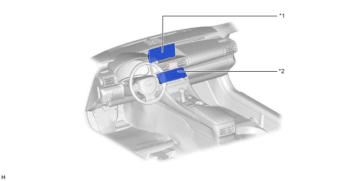
*1 Multi-Display Assembly *2 Air Conditioning Control Assembly Figure 2. Air Conditioning Control Panel Location (RHD Models)
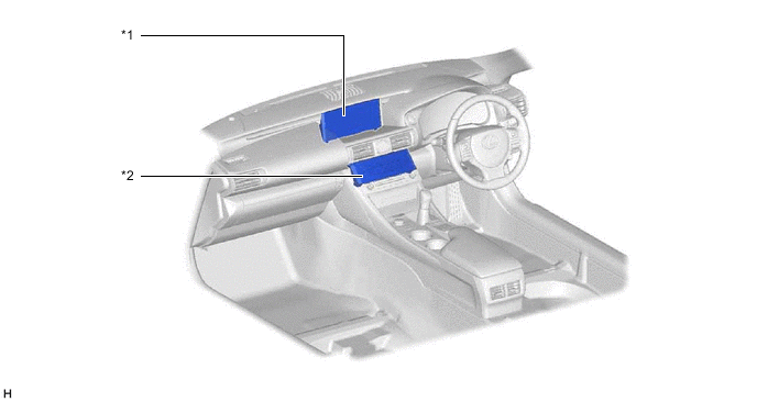
*1 Multi-Display Assembly *2 Air Conditioning Control Assembly Figure 3. Multi-Display Assembly
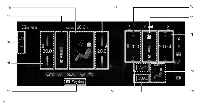
*a Air Outlet Mode Switch *b Airflow Volume Switch *c Sub Menu Switch *d Temperature Control Switch (Left Side) *e Sub Function Menu Switch *f Temperature Control Switch (Right Side) *g A/C Switch *h DUAL Switch *i The illustrations shown are examples only. - - Figure 4. Air Conditioning Control Assembly (LHD Models for Europe)
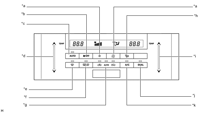
*a Airflow Volume Switch *b Blower Fan Off Switch *c AUTO Switch *d Temperature Control Switch (Driver Side) *e Front Defroster Switch *f Rear Window Defogger and Mirror Heater Switch *g Air Inlet Control Switch *h Air Outlet Mode Switch *i Temperature Control Switch (Front Passenger Side) *j DUAL Switch *k A/C Switch - - Figure 5. Air Conditioning Control Assembly (Models for G.C.C. Countries)
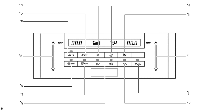
*a Airflow Volume Switch *b Blower Fan Off Switch *c AUTO Switch *d Temperature Control Switch (Driver Side) *e Front Defroster Switch *f Rear Window Defogger Switch *g Air Inlet Control Switch *h Air Outlet Mode Switch *i Temperature Control Switch (Front Passenger Side) *j DUAL Switch *k A/C Switch - - Figure 6. Air Conditioning Control Assembly (LHD Models for General Countries)
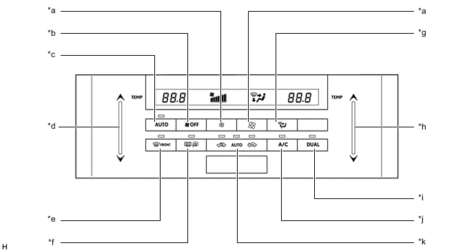
*a Airflow Volume Switch *b Blower Fan Off Switch *c AUTO Switch *d Temperature Control Switch (Driver Side) *e Front Defroster Switch *f Rear Window Defogger and Mirror Heater Switch *g Air Outlet Mode Switch *h Temperature Control Switch (Front Passenger Side) *i DUAL Switch *j A/C Switch *k Air Inlet Control Switch - - Figure 7. Air Conditioning Control Assembly (RHD Models for Europe)
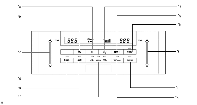
*a Airflow Volume Switch *b Air Outlet Mode Switch *c Temperature Control Switch (Front Passenger Side) *d DUAL Switch *e A/C Switch *f Air Inlet Control Switch *g Blower Fan Off Switch *h AUTO Switch *i Temperature Control Switch (Driver Side) *j Rear Window Defogger and Mirror Heater Switch *k Front Defroster Switch - - Figure 8. Air Conditioning Control Assembly (Models for Australia)
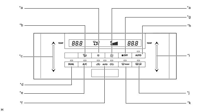
*a Airflow Volume Switch *b Air Outlet Mode Switch *c Temperature Control Switch (Front Passenger Side) *d DUAL Switch *e A/C Switch *f Air Inlet Control Switch *g Blower Fan Off Switch *h AUTO Switch *i Temperature Control Switch (Driver Side) *j Rear Window Defogger and Mirror Heater Switch *k Front Defroster Switch - -
-