AIR CONDITIONING SYSTEM
-
FUNCTION OF MAIN COMPONENTS
-
The air conditioning system consists of the following parts:
Component Function Radio Receiver Assembly Allows operation and adjustment of the air conditioning system via switches. Multi Display Assembly Air Conditioning Amplifier Assembly Transmits and receives data to and from the switches and sensors, and controls the air conditioning system. Cooler Compressor Assembly Performs suction, compression and discharge of refrigerant gas. Blower with Fan Motor Sub-assembly A brushless motor is used to achieve a compact and lightweight assembly. Cooler Condenser Assembly A Global Inner-fin Condenser (GIC) is used to improve heat exchange efficiency. Heater Radiator Unit Sub-assembly A Straight Flow Aluminum-II (SFA-II) heater radiator is used for compactness and high performance. No. 1 Cooler Evaporator Sub-assembly A Revolutionary super-slim Structure (RS) type cooler evaporator sub-assembly is used for compactness and high performance. Evaporator Temperature (No. 1 Cooler Thermistor) Detects the temperature of the cool air just past the cooler evaporator sub-assembly and transmits data to the air conditioning amplifier assembly. Ambient Temperature Sensor (Thermistor Assembly) Detects ambient temperature and outputs it to the air conditioning amplifier assembly. Cooler (Room Temperature Sensor) Thermistor Detects room temperature and outputs it to the air conditioning amplifier assembly. Solar Sensor (Automatic Light Control Sensor) Detects changes in the amount of solar energy and outputs them to the air conditioning amplifier assembly. Damper Servo Sub-assembly Receives the operation signals from the air conditioning amplifier assembly, operates the motor, and opens and closes the dampers. Air Refiner Element Removes pollen, other particles and smell to provide a comfortable interior space. Air Conditioning Pressure Sensor Detects the refrigerant pressure and sends data to the air conditioning amplifier assembly. ECM Receives signals from the engine coolant temperature sensor and transmits them to the air conditioning amplifier assembly. Combination Switch Assembly (Drive Mode Select) Sends the ECO switch operation signal to the air conditioning amplifier assembly. Smog Ventilation Sensor* Detects harmful elements such as CO, HC, and NOx, which are present in the air outside of the vehicle and outputs this information to the air conditioning amplifier assembly. *: Models with automatic recirculation control system
-
-
SYSTEM CONTROL
-
Control List
Control Function Neural Network Control This control is capable of effecting complex control by artificially simulating the information processing method of the nervous system of living organisms in order to establish a complex input/output relationship that is similar to a human brain. Automatic Recirculation Control*1 Automatically changes the air inlet mode to fresh air or recirculate mode according to the level of harmful elements in the outside air, cabin temperature, and outside temperature. Pollen Removal Mode Control
-
Activated by the pollen removal mode switch operation.
-
Sends air which has passed through the air refiner element to the area around the upper part of the bodies of the driver and front passenger. This air has been filtered by the air refiner element in order to remove pollen.
Outlet Air Temperature Control Based on the temperature set at the temperature control switch, the neural network control calculates the outlet air temperature based on the input signals from various sensors. The temperature setting for the driver and front passenger is controlled independently in order to provide a separate vehicle interior temperature for the right and left sides of the vehicle. Thus, air conditioning control that accommodates different occupant preferences has been achieved. The temperature setting for the driver, front passenger and rear passenger is controlled independently in order to provide a separate vehicle interior temperature for the right, left and rear sides of the vehicle. Thus, air conditioning control that accommodates different occupant preferences has been achieved. Blower Control Controls the blower motor in accordance with the airflow volume that has been calculated by neural network control based on the input signals from various sensors. Automatically increases the blower level when the defroster is on. Air Outlet Control Automatically switches the air outlets in accordance with the outlet mode that has been calculated by neural network control based on the input signals from various sensors. In accordance with the engine coolant temperature, outside air temperature, amount of sunlight, required blower, outlet temperature and vehicle speed conditions, this control automatically switches the blower outlet to FOOT/DEF mode to prevent the windows from becoming fogged when the outside air temperature is low. Air Inlet Control Automatically controls the air inlet control damper to achieve the calculated outlet air temperature that is required. Drives the servo motor (for air inlet) in accordance with the operation of the air inlet control switch and moves the dampers to the FRESH or RECIRC position. Cooler Compressor Control Through the calculation of the target evaporator temperature based on various sensor signals, the air conditioning amplifier assembly optimally controls the discharge capacity by regulating the opening extent of the solenoid control valve. Turns the air conditioning on automatically by pressing the AUTO button when the blower is on and the air conditioning is off. Evaporator Control When set to automatic, cooler compressor variable capacity operation is controlled to save power. When set to manual, cooler compressor variable capacity operation is controlled for maximum cooling to dehumidify air and prevent the windows from fogging up. Memory Call Control*2 Memorizes the last air conditioning settings when the engine switch is turned from on (IG) to off in accordance with the ID code of the electrical key transmitter sub-assembly that is used to operate the vehicle. The memory call control then recalls the settings if the electrical key transmitter sub-assembly is used when the engine switch is turned on (IG). This function operates when both of the following conditions are met:
-
Inside of the outside door handle is touched or the driver door is unlocked using the unlock button, and then the driver door is opened.
-
Engine switch is turned on (IG).
Rear Window Defogger Control
-
Switches the rear defogger and outside rear view mirror heaters on for 15 minutes when the rear defogger and mirror heater switch is pressed.
-
Switches the rear defogger and outside rear view mirror heaters off if the button is pressed while they are operating.
Front Wiper Deicer Control*3 Switches the front wiper deicer to on for approximately 15 minutes when the front wiper deicer switch is pressed. Outside Temperature Indication Control Based on the signals from the thermistor assembly, this control calculates the outside temperature, this value is then corrected in the air conditioning amplifier, and shown on the multi-information display. ECO Drive Mode Control When set to ECO drive mode, the air conditioning amplifier assembly decreases the blower speed. Blower Customization Control*4 The air volume can be adjusted in 3 levels using the FAST SOFT switch: MEDIUM → SOFT (small air volume) → FAST (large air volume) Diagnosis A Diagnostic Trouble Code (DTC) is stored in memory when the air conditioning amplifier assembly detects a problem in the air conditioning system. *1: Models with automatic recirculation control system
*2: Models with position memory function
*3: Models with front wiper deicer system
*4: Models for blower customization control
-
-
Neural Network Control
-
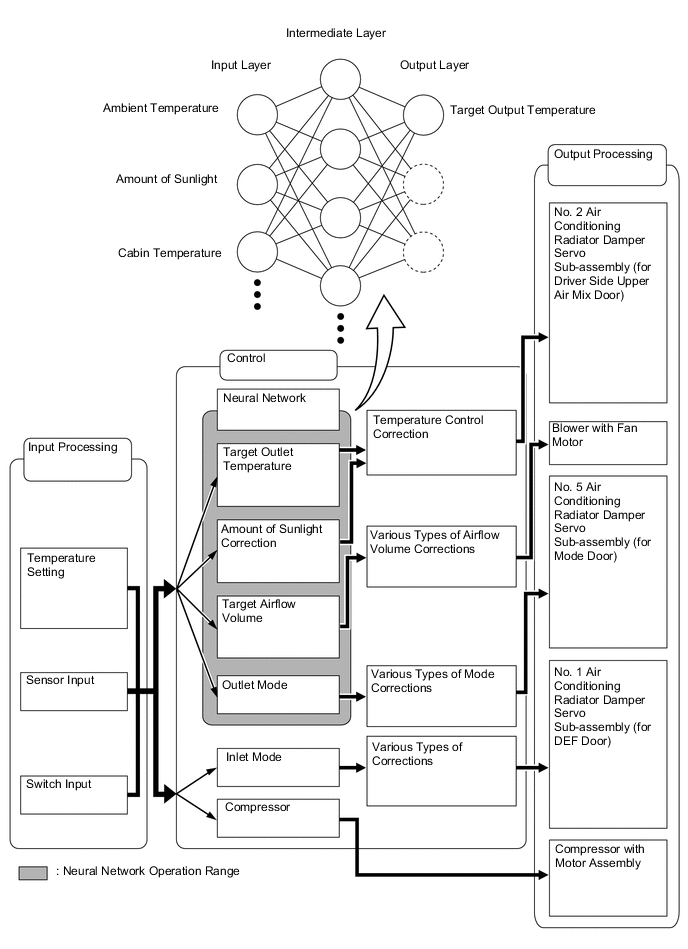
Previously, in automatic air conditioning systems without neural network control, the air conditioning amplifier assembly determined the required outlet air temperature and blower air volume in accordance with a calculation formula that had been obtained based on information received from the sensors. However, because the senses of a person are rather complex, a given temperature is sensed differently depending on the environment in which the person is situated. For example, a given amount of solar radiation can feel comfortably warm in a cold climate, or extremely uncomfortable in a hot climate. Therefore, as a technique for effecting a higher level of control, a neural network has been adopted in the automatic air conditioning system. With this technique, the data that has been collected under varying environmental conditions is stored in the air conditioning amplifier assembly. The air conditioning amplifier assembly can then effect control to provide enhanced air conditioning comfort.
-
The neural network control consists of neurons in the input layer, intermediate layer and output layer. The input layer neurons process the input data of the ambient temperature, the amount of sunlight, and the room temperature based on the signals of the switches and sensors, and output them to the intermediate layer neurons. Based on this data, the intermediate layer neurons adjust the strength of the links among the neurons. The sum of these is then calculated by the output layer neurons in the form of the required outlet temperature, solar correction, target airflow volume, and outlet mode control volume. Accordingly, the air conditioning amplifier assembly controls the servo motors and blower motor in accordance with the control volumes that have been calculated by neural network control.
-
-
Automatic Recirculation Control (Models with Automatic Recirculation Control System)
-
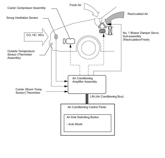
When the automatic recirculation control is operating, the air conditioning amplifier assembly automatically changes the air inlet mode to fresh air or recirculate air mode based on signals from the smog ventilation sensor, outside temperature sensor (thermistor assembly), and cooler (room temp. sensor) thermistor when AUTO air inlet mode is selected.
-
The air conditioning amplifier assembly detects harmful elements (CO, HC and NOx) based on smog ventilation sensor signals and automatically switches the air inlet mode to recirculate air mode to prevent such harmful elements from entering the cabin.
-
The air conditioning amplifier assembly detects room temperature based on a cooler (room temp. sensor) thermistor signal and automatically switches the air inlet mode to recirculate air mode to prevent the room temperature from becoming too high.
-
The air conditioning amplifier assembly detects outside temperature based on a outside temperature sensor (thermistor assembly) signal and automatically switches air inlet mode to fresh air mode to prevent the windshield from fogging up.
Tech Tips
The smog ventilation sensor cannot detect elements such as smoke from a bonfire or factory exhaust, foul or animal odors, and dirt or dust particles. Therefore, air inlet mode is not switched in accordance with those elements. Depending on the direction of the wind, the smog ventilation sensor might not be able to detect the undesirable elements (CO, HC and NOx), allowing them to enter the cabin.
-
-
-
ECO Drive Mode Control
-
During ECO drive mode, the air conditioning amplifier assembly restricts air conditioning system performance under specified conditions, thus improving fuel economy.
-
The ECO drive mode control is activated when the combination switch assembly (drive mode select) is operated, and then restricts air conditioning system performance as described below:
Control Outline Inside/outside Air Switch Control Automatically switches the air inlet port to the internal air circulation mode when the outside air temperature is equal to or higher than a predetermined temperature, reducing power consumption. Blower Level Control Sets the blower level in AUTO mode lower than normal, and reduces power consumption. Seat Heater Control When the ECO drive mode is selected, the air conditioning amplifier assembly turns on the front seat heater system in accordance with the air outlet mode (front seat control mode or driver seat control mode), outside temperature and room temperature. For details, refer to the seat heater system.
-
-
Pollen Removal Mode Control
-
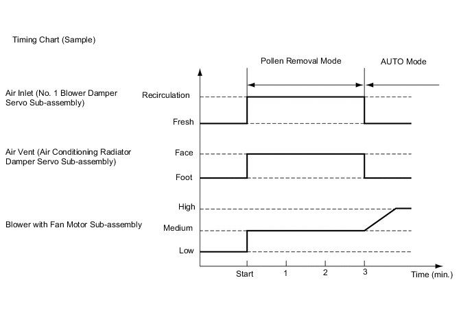
When the pollen removal switch is pressed, the pollen removal mode control is activated. The air vent is switched to FACE mode and recirculated pollen-free air flows around the upper body areas of the driver and front passenger.
-
When the pollen removal switch signal is received by the air conditioning amplifier assembly, the air conditioning amplifier assembly controls the No. 1 blower damper servo sub-assembly, air conditioner radiator damper servo and blower with fan motor sub-assembly as shown in the timing chart below.
-
This control usually operates for approximately 3 minutes. However, when the outside temperature is low, the control will operate for approximately 1 minute.
-
After this control stops operating, the air conditioning amplifier assembly controls the air conditioning system using AUTO mode.
-
-
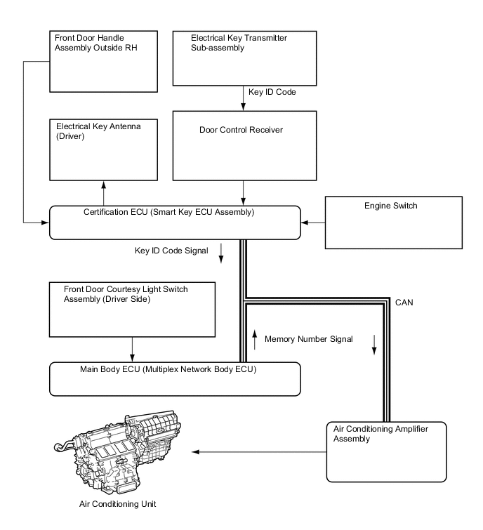
Memory Call Control
-
The air conditioning amplifier assembly stores the air conditioning settings for each memory number when the engine switch is turned off.
-
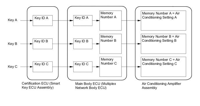
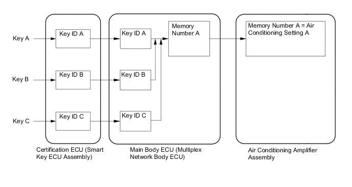
The main body ECU (multiplex network body ECU) converts the key ID code into a memory number, stores it and sends the converted signal to the air conditioning amplifier assembly.
-
The air conditioning amplifier assembly stores the memory number and air conditioning settings.
-
When the doors are unlocked, the certification ECU (smart key ECU assembly) recognizes the key ID code and sends it to the main body ECU (multiplex network body ECU).
-
Upon receiving the key ID code signal, the main body ECU (multiplex network body ECU) converts the signal into a memory number signal and sends it to the air conditioning amplifier assembly.
-
Then the air conditioning amplifier assembly recalls the stored air conditioning settings based on the memory number signal when the engine switch is turned on (IG).
-
The following air conditioning system settings can be memorized:
Setting Condition Air Conditioning Switch On or Off AUTO Switch On or Off Temperature Setting Driver LO, 16°C to 32°C (65°F to 85°F) or HI Front Passenger LO, 16°C to 32°C (65°F to 85°F) or HI Blower Fan Speed Level 1 to 7 Air Inlet Mode Fresh or Recirculate Air Outlet Mode Face, Bi-level, Foot, Foot and Defroster or Defroster Tech Tips
-
Memory call control of the air conditioning system can be canceled or re-enabled using the Global TechStream (GTS).
-
The main body ECU (multiplex network body ECU) can store a maximum of 3 memory numbers.
-
The memory call function recalls the key ID that was recognized when the door was unlocked. This happens even when the user brings 2 keys or more, or the user uses different keys to unlock the door and to turn the engine switch on (IG).
-
Using the Global TechStream (GTS), the main body ECU (multiplex network body ECU) can be made to convert the ID numbers of different keys to a desired memory number. Therefore, all key IDs can be converted to an identical memory number, or 2 memory numbers can be divided among 3 keys.
-
For details about key ID code registration, refer to the Repair Manual.
-
-
-
-
DIAGNOSIS
-
The air conditioning amplifier assembly has a self-diagnosis function. It stores any operation malfunctions in the air conditioning system or heater system in memory in the form of Diagnostic Trouble Codes (DTCs). For details, refer to the Repair Manual.
-