METER / GAUGE SYSTEM
-
FUNCTION
-
Multi Buzzer
-
The table below shows the warning and reminder functions of the buzzer in the combination meter assembly.
Priority Item 1 Engine Start while Driving Notice 2 Engine Switch Operation while Driving Warning 3 Front Seat Belt Warning (Level 2) 4 Rear Seat Belt Warning*1 5 Front Seat Belt Warning (Level 1) 6 Unexpected Vehicle Motion Warning 7 Brake Fluid Low Warning 8 Engine Oil Pressure Warning 9 EPS Warning 10 Engine Coolant Temperature Warning 11 Door Open when Shift Lever not in P Warning 12 Entry and Start System Warning (Continuous) 13 Entry and Start System Warning 1 (Intermittent) 14 Entry and Start System Warning 2 (Intermittent) 15 Entry and Start System Warning (Once) 16 Lane Departure Alert Warning*2 17 Multi-information Display Warning 18 Dynamic Radar Cruise Control Cancelation due to Low Speed Warning*3 19 Immobiliser Certification Reminder 20 Speed Limit Exceed Warning*4 21 Parking Brake Engaged Warning 22 Door Open while Driving Warning 23 Sport Shift Reject Warning 24 Light Reminder*5 25 Turn Signal/Hazard Warning Operation *1: Models with rear seat belt warning function
*2: Models with lane departure alert system
*3: Models with dynamic radar cruise control system
*4: Models for G.C.C. counties
*5: Models for Europe and destination package for South Africa
-
-
Multi-information Display
-
Display Function Flow
-
The multi-information display can be switched as shown in the flow chart below:
Figure 1. Models with Optitron Meter
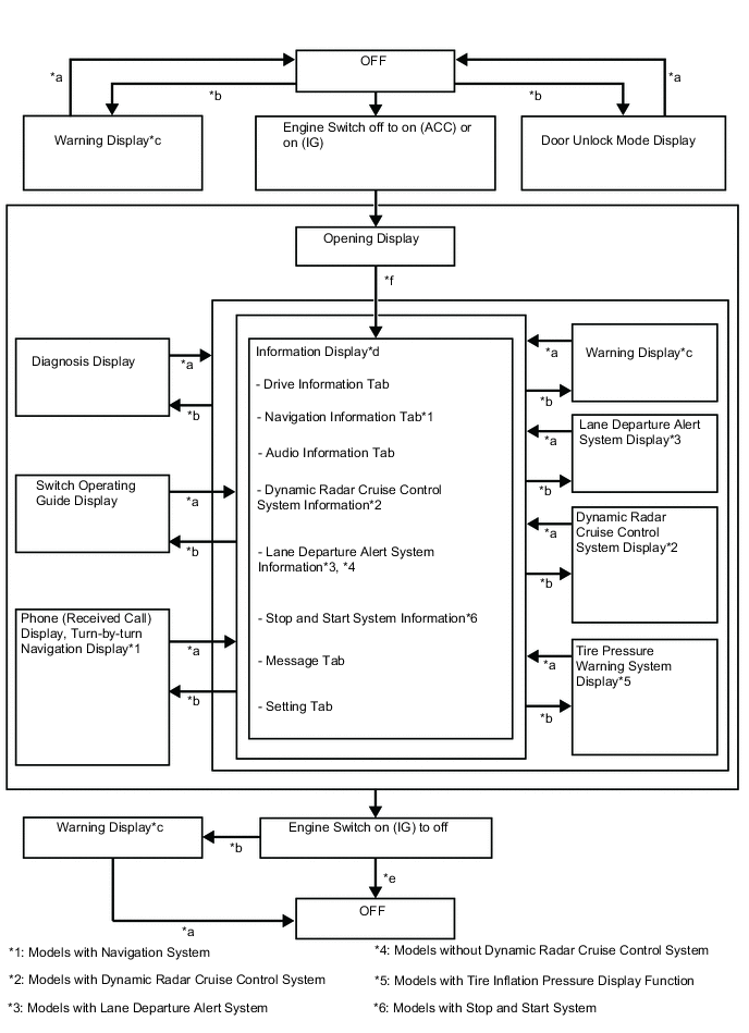
Item Display Change Condition *a Conditions are not met. *b Conditions are met. *c If there are multiple display requests, items will be displayed in sequence. *d An item or display is selected by operating the steering pad switch assembly. *e ODO display is displayed for a certain period of time after the engine switch is turned off. *f After engine switch on (IG). Figure 2. Models with TFT LCD Meter
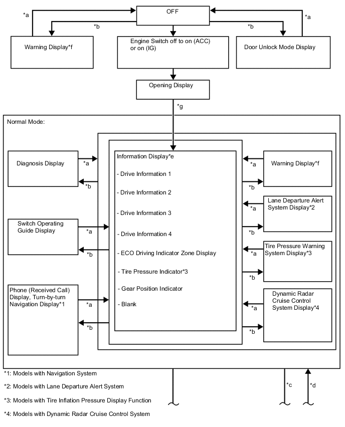
Item Display Change Condition *a Conditions are not met. *b Conditions are met. *c TOP switch operated. *d Movable meter ring activated. *e An item or display is selected by operating the steering pad switch assembly. *f If there are multiple display requests, items will be displayed in sequence. *g After engine switch on (IG). 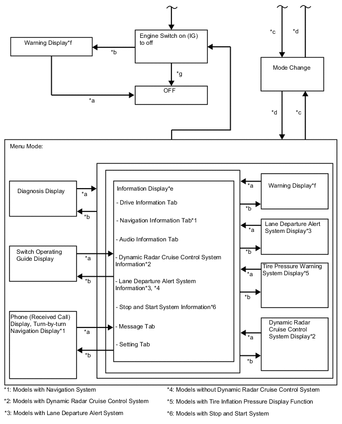
Item Display Change Condition *a Conditions are not met. *b Conditions are met. *c TOP switch operated. *d Movable meter ring activated. *e An item or display is selected by operating the steering pad switch assembly. *f If there are multiple display requests, items will be displayed in sequence. *g ODO display is displayed for a certain period of time after the engine switch is turned off.
-
-
Display Tab Operation (Optitron Meter and TFT LCD Meter)
-
The information currently displayed can be switched using the RIGHT/LEFT switch of the steering pad switch assembly.
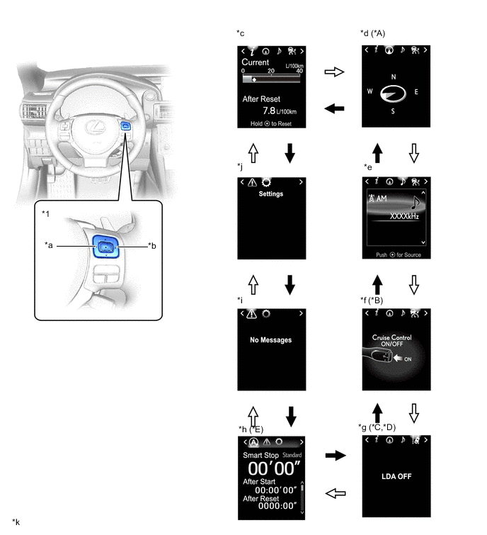
*A Models with Navigation System *B Models with Dynamic Radar Cruise Control System *C Models with Lane Departure Alert System *D Models without Dynamic Radar Cruise Control System *E Models with Stop and Start System - - *1 Steering Pad Switch Assembly - - *a LEFT Switch *b RIGHT Switch *c Drive Information *d Navigation Information *e Audio Information *f Dynamic Radar Cruise Control System Information *g Lane Departure Alert System Information *h Stop and Start System Information *i Message *j Settings *k The illustrations shown are examples only. - - 
RIGHT switch operation 
LEFT switch operation
-
-
Drive Information (Optitron Meter and TFT LCD Meter in Menu Mode)
-
The drive information tab shows vehicle information such as drivable range and fuel consumption.
-
The drive information display can be changed using the UP/DOWN switch of the steering pad switch assembly.
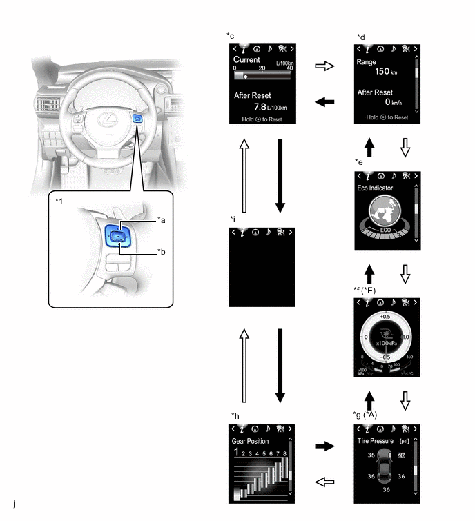
*A Models with Tire Inflation Pressure Display Function *B Models with 8AR-FTS Engine *1 Steering Pad Switch Assembly - - *a UP Switch *b DOWN Switch *c Drive Information 1 *d Drive Information 2 *e ECO Driving Indicator Zone Display *f Boost Meter / Oil Pressure Gauge / Oil Temperature Gauge *g Tire Pressure Indicator *h Gear Position Indicator *i Blank j The illustrations shown are examples only. DOWN switch operation UP switch operation
-
-
Information (TFT LCD Meter in Normal Mode)
-
The drive information tab shows vehicle information such as drivable range and fuel consumption.
-
The information currently displayed can be changed using the UP/DOWN switch of the steering pad switch assembly.
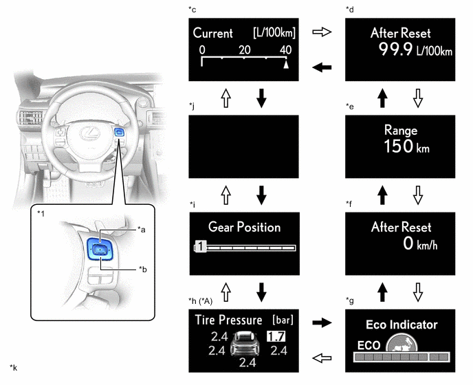
*A Models with Tire Inflation Pressure Display Function - - *1 Steering Pad Switch Assembly - - *a UP Switch *b DOWN Switch *c Drive Information 1 (Upper Area) *d Drive Information 1 (Lower Area) *e Drive Information 2 (Upper Area) *f Drive Information 2 (Lower Area) *g ECO Driving Indicator Zone Display *h Tire Pressure Indicator *i Gear Position Indicator *j Blank *k The illustrations shown are examples only. - - DOWN switch operation UP switch operation
-
-
Stop and Start System Information Mode Function (Models with Stop and Start System)
-
Stop and start system information shows vehicle information such as idling stop time and saved fuel.
-
The stop and start system information can be switched using the UP/DOWN switch on the steering pad switch assembly.
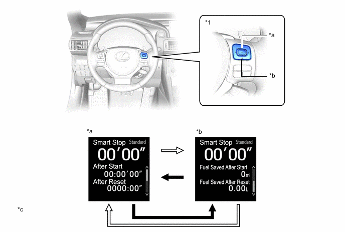
*1 Steering Pad Switch Assembly - - *a UP Switch *b DOWN Switch *c Total Amount of Engine Stoppage Time / Amount of Engine Stoppage Time After Engine Start-up / Amount of Engine Stoppage Time Between Reset Operations *d Total Amount of Engine Stoppage Time / Amount of Saving Fuel After Engine Start-up / Amount of Saving Fuel Between Reset Operations *e The illustrations shown are examples only. - - DOWN switch operation UP switch operation
-
-
Setting Function
-
The items displayed on the multi-information display can be customized.
-
The following items can be selected on the information setting screen.
Item Available Setting Language
-
The language used on the multi-information display can be selected:
-
English
-
French
-
Spanish
-
German*1
-
Italian*1
-
Russian*1
-
Chinese*2
Unit
-
The unit displayed on the multi-information display can be selected:
-
miles (MPG)*1
-
km (L/100 km) (Default*3)
-
km (km/L) (Default*4)
Eco Driving Indicator Light
-
The Eco Driving Indicator Light can be switched:
-
ON (Default)
-
OFF
Drive Information 1
-
2 items can be selected among the following:
-
Current Fuel Consumption (Bar Display)/Average Fuel Consumption (Mark Display) (Default of upper area)
-
Total Average Fuel Consumption Between Reset Operations (Default of lower area)
-
Average Fuel Consumption After Engine Start-up
-
Average Fuel Consumption After Refueling
-
Total Average Vehicle Speed Between Reset Operations
-
Average Vehicle Speed After Engine Start-up
-
Cruising Range After Engine Start-up
-
Total Elapsed Time Between Reset Operations
-
Elapsed Time After Engine Start-up
-
Cruising Range
-
Blank
Drive Information 2
-
2 items can be selected among the following:
-
Current Fuel Consumption (Bar Display)/Average Fuel Consumption (Mark Display)
-
Total Average Fuel Consumption Between Reset Operations
-
Average Fuel Consumption After Engine Start-up
-
Average Fuel Consumption After Refueling
-
Total Average Vehicle Speed Between Reset Operations (Default of lower area)
-
Average Vehicle Speed After Engine Start-up
-
Cruising Range After Engine Start-up
-
Total Elapsed Time Between Reset Operations
-
Elapsed Time After Engine Start-up
-
Cruising Range (Default of upper area)
-
Blank
TOP Switch Settings*5
-
The item that is displayed when the TOP switch is pressed can be selected among the following:
-
Drive Information 1 (Default)
-
Drive Information 2
-
ECO Driving Indicator Zone Display
-
Tire Pressure Indicator*6
-
Gear Position Indicator
-
Blank
-
Navigation Information*7
-
Audio Information
-
Dynamic Radar Cruise System Information*8
-
Lane Departure Alert System Information*9, *10
-
Message
-
Settings
Interruption Display
-
The following displays that appear as soon as the set conditions are met can be switched to ON (Default) or OFF:
-
Turn-by-turn Navigation Display*7
-
Incoming Telephone Display
-
Dynamic Radar Cruise Control Switch Operation Guide*8
-
Rheostat
-
Ring Guidance*11
Accent Color*5
-
The accent color can be changed:
-
White Heat (Default)
-
Titanium Silver
Needle Color*11
-
The needle color of the tachometer can be changed:
-
Blue (Default)
-
Red
-
White
Vehicle Speed Warning*11, *12
-
The vehicle speed warning can be switched:
-
ON
-
OFF (Default)
Tech Tips
-
The vehicle speed for warning activation can be set at increments of 1 km/h between 50 and 120 km/h*13 or 50 and 200 km/h*14.
-
The maximum value varies according to the countries and regions.
Rev Indicator*11
-
The rev indicator setting can be switched:
-
ON (Default at 5000 rpm)
-
OFF
Tech Tips
The engine speed for rev indicator activation can be set at increments of 100 rpm between 2000 rpm and 6600 rpm.
Tachometer Peak Hold Function*11
-
The tachometer peak hold function can be switched:
-
ON (Default)
-
OFF
Initialization The set items can be initialized. *1: Models for Europe
*2: Except models for Europe
*3: Except destination package for South Korea
*4: Destination package for South Korea
*5: Models with optitron meter
*6: Models with tire inflation pressure display function
*7: Models with navigation system
*8: Models with dynamic radar cruise control system
*9: Models with lane departure alert system
*10: Models without dynamic radar cruise control system
*11: Models with TFT LCD meter
*12: Except models for G.C.C. countries
*13: Destination packages for Taiwan and South Korea
*14: Except destination packages for Taiwan and South Korea
-
-
-
Warning Mode Function
-
When a warning is necessary, the warning display interrupts the current display on the multi-information display.
-
The master warning light may illuminate or blink and the buzzer in the combination meter assembly may sound depending on the item displayed on the multi-information display.
Priority Display Master Warning Light Buzzer 1 VGRS Test Mode*1 - - Adjusting LDA Camera*2 - - Adjusting Front Radar Beam*3, *4 - - Checking Cruise Control C/D*3 - - Checking Cruise Control Brake*3 - - BRAKE!*4 - -*5 Holding in Engine Switch Will Cause an Emergency Engine Stop. Blinks Sounds To Restart Car, Shift Lever to "N" and Press Engine Switch. Blinks Sounds The Engine Has Stopped. Please Put Shift Lever into "P". Blinks Sounds The Engine Has Stopped. Please Stop Your Car in a Safe Place. Blinks Sounds 2 Dynamic radar cruise control warning reminder indicator (image display)*3 - - Lane departure alert warning reminder indicator (image display)*2 - - Brake Malfunction Blinks Sounds The Accelerator is Stuck. Please Depress Brake Pedal to Stop Car. Blinks Sounds 3 Door open (while driving)*6 Blinks Sounds Door open - - Clearance sonar detection (image display)*7 - - Check Park Sonar System*7 Illuminates - Clean Park Sonar*7 Illuminates - 4 Auto Power OFF to Conserve Battery - - 5 Shift to P position when parked Blinks Sounds EPS Failure. Steering Wheel Harder to Turn. Illuminates Sounds Voltage Abnormality. Steering Wheel Harder to Turn. Illuminates Sounds Check Power Steering System Illuminates Sounds Release Parking Brake Blinks Sounds Key not detected Blinks Sounds 6 1st Gear not available due to slippery road surface Illuminates Sounds Speed Limit Exceeded*8 Blinks Sounds 7 Check SRS Airbag System Illuminates Sounds Check ABS - Sounds Engine Coolant High Temperature Illuminates Sounds Clean Radar Sensor*3, *4 Illuminates Sounds Cruise Control not available*3 Illuminates Sounds LDA not available*2 Illuminates Sounds Check Entry & Start System Blinks Sounds BSM not available*9 Illuminates Sounds Check Cruise Control System*3 Illuminates Sounds Check LDA System*2 Illuminates Sounds Check PCS System*4 Illuminates Sounds Check BSM System*9 Illuminates Sounds Engine Oil Pressure Low Illuminates Sounds Transmission Fluid High Temperature Illuminates Sounds Check VGRS System*1 Illuminates Sounds Check DRS System*1 Illuminates Sounds POP UP HOOD Activated.*10 Illuminates Sounds POP UP HOOD Failure.*10 Illuminates Sounds LDA System is Unavailable Below Approx. 50 km/h.*2 - - LDA System is Unavailable at this Speed.*2 - - 8 Dynamic radar cruise control indicator (image display)*3 - - Lane departure alert indicator (image display)*2 - - Engine Stopped, Steering Wheel Harder to Turn. Illuminates Sounds Turn Power OFF Blinks Sounds Key detected in vehicle Blinks Sounds Turn Light Off Blinks Sounds Moon Roof opened*11 Blinks Sounds Window opened Blinks Sounds Window/Moon Roof opened*11 Blinks Sounds Depress brake pedal, touch engine switch with key Blinks Sounds Depress brake pedal and push engine switch to start - - Depress brake pedal and push engine switch to start - Sounds The Accelerator is Stuck. Please Check the Accelerator. Blinks Sounds 9 Steering Lock active Blinks Sounds Brake Override System Failure. Illuminates Sounds 10 Key Battery Low Illuminates Sounds Engine Oil Level Low Illuminates Sounds Check Headlight System Illuminates Sounds Both Accelerator and Brake Pedals Are Depressed. Blinks - Tire pressure indicator (image display)*12 - - 11 Check VGRS System*1 Illuminates - Check DRS System*1 Illuminates - Washer Fluid Low - - Fuel Low - - TRC OFF - - Injector Maintenance required soon*13 Illuminates - Injector Maintenance required*13 Illuminates - Turn on the high beam to activate AHB System*14 - - Depress brake pedal and push engine switch to start - - VSC System Switched Off. Pre-Crash Brake System Disengaged.*4 - - PCS temporarily not available*4 - - Operation of Electrical Items Restricted. - - Theft Sensor OFF - - Theft Sensor ON - - *1: Models with variable gear ratio steering system
*2: Models with lane departure alert system
*3: Models with dynamic radar cruise control system
*4: Models with pre-crash safety system
*5: Skid control buzzer operation is activated.
*6: If the vehicle has reached a speed of 5 km/h (3 mph)
*7: Models with Lexus parking assist-sensor system
*8: Models for G.C.C. countries
*9: Models with blind spot monitor system
*10: Models with pop up hood
*11: Models with sliding roof system
*12: Models with tire inflation pressure display function
*13: Models with injector maintenance required reminder function
*14: Models with automatic high beam system
-
-
-
-
OPERATION
-
Eco Driving Indicator Light and ECO Driving Indicator Zone Display
-
The following table shows the operation of Eco Driving Indicator Light and ECO Driving Indicator Zone Display in different driving conditions:
Optitron Meter and TFT LCD in Menu Mode Driving Condition Eco Driving Indicator Light ECO Driving Indicator Zone Display While Stopped Turns off 
While Eco Driving Turns on 
While Non-eco Driving Turns off 
When any of the following conditions is met, operation is stopped.
-
Engine switch off.
-
Engine stopped.
-
Shift lever is not in D.
-
A paddle shift switch is operated.
-
NORMAL mode or ECO mode not selected.
-
The vehicle is being driven at a speed of 130 km/h (81 mph) or higher.
Turns off TFT LCD in Normal Mode Driving Condition Eco Driving Indicator Light ECO Driving Indicator Zone Display While Stopped Turns off 
While Eco Driving Turns on 
While Non-eco Driving Turns off 
When any of the following conditions is met, operation is stopped.
-
Engine switch off.
-
Engine stopped.
-
Shift lever is not in D.
-
A paddle shift switch is operated.
-
NORMAL mode or ECO mode not selected.
-
The vehicle is being driven at a speed of 130 km/h (81 mph) or higher.
Turns off -
-
-