VARIABLE GEAR RATIO STEERING
-
STRUCTURE
-
The steering actuator assembly consists of a housing, motor, reduction mechanism, lock mechanism and output shaft. The rotational movement of the steering wheel is transmitted from the housing to the output shaft via a reduction mechanism. Since the steering actuator assembly rotates during steering operation, a spiral cable is used to supply power to the motor.
-
The reduction mechanism consists of a stator gear, driven gear, flexible gear and wave generator. When the motor is rotated by the power output from the front steering control ECU, the wave generator rotates to generate the wave movement of the flexible gear. Each rotation of the wave generator causes the driven gear to rotate a comparatively small angle, resulting in a highly reduced gear ratio. By using the motor and reduction system to add to or subtract from the drivers steering input, the angle of the front wheels can be controlled in combination with the steering wheel rotation.
-
When a malfunction is detected in the variable gear ratio steering system, the lock mechanism mechanically locks the motor to directly connect the housing to the output shaft, ensuring normal steering operation.
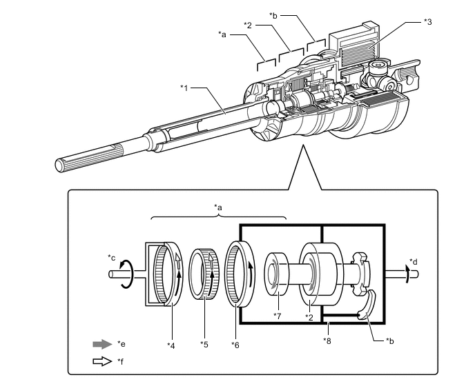
*1 Output Shaft *2 Motor *3 Spiral Cable *4 Driven Gear (100 teeth) *5 Flexible Gear (100 teeth) *6 Stator Gear (102 teeth) *7 Wave Generator *8 Housing *a Reduction Mechanism *b Lock Mechanism *c Output Shaft Rotation *d Steering Wheel Rotation *e Motor Rotation *f VGRS Rotation Angle -
Reduction Mechanism
-
The reduction mechanism uses a strain wave gear system, which is compact and highly accurate, and creates a large reduction gear ratio using a small number of components.
-
This reduction mechanism consists of a stator gear, driven gear, flexible gear and wave generator. The flexible gear is deformed by the rotational movement of the wave generator, creating a difference in the rotational amount of the stator gear and driven gear.
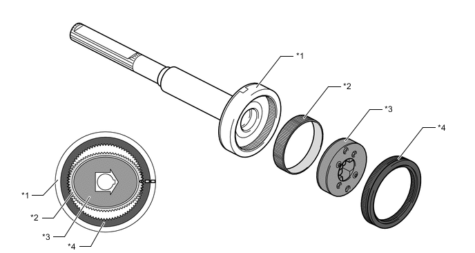
*1 Driven Gear (100 teeth) *2 Flexible Gear (100 teeth) *3 Wave Generator *4 Stator Gear (102 teeth) Construction of Reduction Mechanism Item Construction Stator Gear (Input)
-
Has a rigid body and a ring shape, and contains 102 teeth along the inner circumference.
-
Positioned parallel to the driven gear.
-
Coupled to the housing of the steering actuator assembly.
Driven Gear (Output)
-
Has a rigid body and a ring shape, and contains 100 teeth along the inner circumference.
-
Positioned parallel to the stator gear.
-
Coupled to the output shaft of the steering actuator assembly.
Flexible Gear
-
Has a flexible metal body that forms a belt shape and contains 100 teeth along the outer circumference.
-
Located outside of the wave generator, and positioned in such a way that its gear teeth are meshed with the inside of both the stator gear and the driven gear.
Wave Generator
-
Consists of an oval-shaped cam and a ball bearing that is fitted around the cam.
-
Coupled to the motor shaft of the motor and rotates inside the flexible gear while pushing the flexible gear against the stator gear and the driven gear.
-
-
The flexible gear is deformed into an oval-shape by the wave generator. The teeth of the flexible gear at the long axis are meshed with the teeth of the stator gear, while the teeth at the short axis are disengaged. (Reduction Mechanism Operation A)
-
For every rotation of the wave generator, each tooth of the flexible gear is disengaged from the stator gear and engaged in a new position. (Reduction Mechanism Operation B)
-
When the wave generator makes one clockwise rotation, the flexible gear moves counterclockwise by 2 teeth because the flexible gear has 2 fewer teeth than the stator gear. The difference between the stator gear operation and driven gear rotation is the VGRS operating angle. (Reduction Mechanism Operation C)
Figure 1. Reduction Mechanism Operation
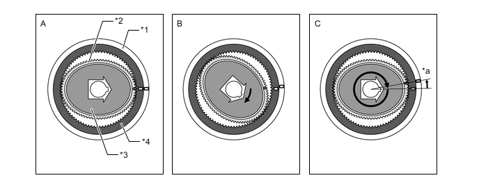
*1 Driven Gear (100 teeth) *2 Flexible Gear (100 teeth) *3 Wave Generator *4 Stator Gear (102 teeth) *a Flexible gear moves counterclockwise by 2 teeth - -
-
-
Motor
-
A compact, high power output and low noise brushless type motor is used.
-
This motor mainly consists of a motor case, coil, magnet, motor shaft and rotation angle sensor.
-
The motor is built into the housing of the steering actuator assembly. One side of the motor shaft is coupled to the wave generator of the reduction mechanism and the other side to the lock holder of the lock mechanism.
-
The rotation angle sensor detects the rotational direction and angle of the motor.
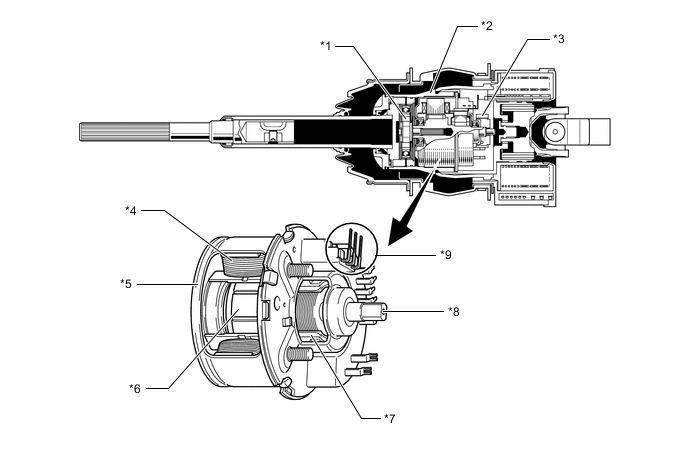
*1 Wave Generator *2 Housing *3 Lock Holder *4 Coil *5 Motor Case *6 Magnet *7 Rotation Angle Sensor *8 Motor Shaft *9 End caps of coil (spiral cable side) - -
-
-
Lock Mechanism
-
The lock mechanism mainly consists of a lock solenoid, lock lever, and a lock holder that is secured to the motor shaft.
-
When a malfunction is detected in the variable gear ratio steering system or the engine switch is turned off, power supply to the lock solenoid is cut off, causing the lock lever to engage with the lock holder due to the return spring. This secures the motor shaft, ensuring normal steering performance.
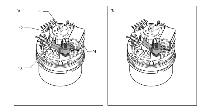
*1 Motor Shaft *2 Lock Holder *3 Lock Lever *4 Lock Solenoid *a Normal *b Locked State
-
-
Spiral Cable
-
Since the steering actuator assembly rotates in response to the steering operation, a spiral cable is used between the motor, lock solenoid, rotation angle sensor and the vehicle harness.
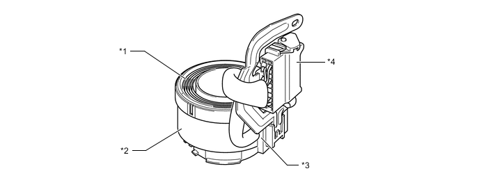
*1 Flexible Flat Cable *2 Case *3 Lead Outlet *4 Connector
-
-