AUTOMATIC TRANSMISSION SYSTEM
-
CONSTRUCTION
-
This automatic transmission uses the transmission revolution sensor (NT), transmission revolution sensor (NC3) and transmission revolution sensor (SP2). Thus, the ECM can detect the timing of the shifting of the gears and appropriately control the engine torque and hydraulic pressure in response to various conditions. These transmission revolution sensors are Hall type.
-
The transmission revolution sensor (NT) detects the input speed of the transmission. The input shaft is used as the timing rotor for this sensor.
-
The transmission revolution sensor (NC3) detects the speed of the intermediate shaft. The No. 3 clutch (C3) drum is used as the timing rotor for this sensor.*1
-
The transmission revolution sensor (NC3) detects the speed of the intermediate shaft. The middle sun gear input drum is used as the timing rotor for this sensor.*2
-
The transmission revolution sensor (SP2) detects the speed of the output shaft. The rear planetary ring gear is used as the timing rotor for this sensor.
-
The Hall type transmission revolution sensor consists of a magnet and Hall IC. The Hall IC converts the changes in the magnetic flux density that occur through the rotation of the timing rotor into an electric signal, and outputs the signal to the ECM.
Tech Tips
*1: Models with 2GR-FKS engine
*2: Models with 8AR-FTS engine
Figure 1. Models with 2GR-FKS engine
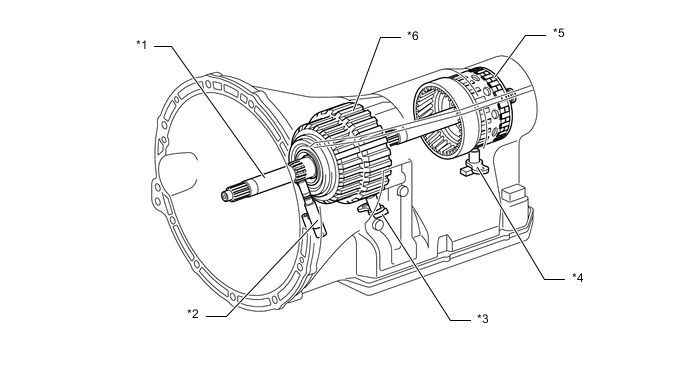
*1 Input Shaft *2 Transmission Revolution Sensor (NT) *3 Transmission Revolution Sensor (NC3) *4 Transmission Revolution Sensor (SP2) *5 Rear Planetary Ring Gear *6 No. 3 Clutch Drum Figure 2. Models with 8AR-FTS engine
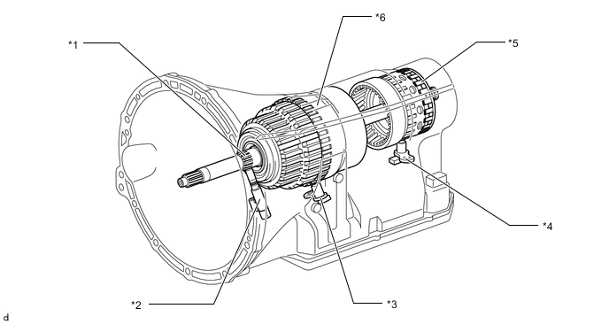
*1 Input Shaft *2 Transmission Revolution Sensor (NT) *3 Transmission Revolution Sensor (NC3) *4 Transmission Revolution Sensor (SP2) *5 Rear Planetary Ring Gear *6 Middle Sun Gear Input Drum
-