FUEL SYSTEM
-
CONSTRUCTION
-
The injection angle of the fuel injector assembly (for direct injection) has been optimized, injection pressure has been increased to produce highly atomized mist, and high fuel dispersion is achieved by performing injection using high tumble airflow. This results in improved engine performance.
-
A solid insulator is used in the head contact area, achieving weight reduction.
-
A fan-shaped spray form, which restrains spray penetration that spreads outward during fuel injection, is used to reduce the amount of fuel that clings to the bore and improve emission performance.
-
The injection volume dynamic range has been expanded and superior high-temperature characteristics have been achieved by optimizing movable parts and magnetic circuits. As a result, fuel economy and emission performance have also been improved.
-
An O-ring and backup ring* are used in the fuel injector assembly (for direct injection). As a result, the transmission of operation noise from the fuel injector assembly (for direct injection) is reduced to improve quietness and ensure fastener airtightness.
Tech Tips
*: The backup ring is installed to securely support the rubber O-ring, which is subjected to high pressures. Take care to install the backup ring in the correct direction at the correct installation position.
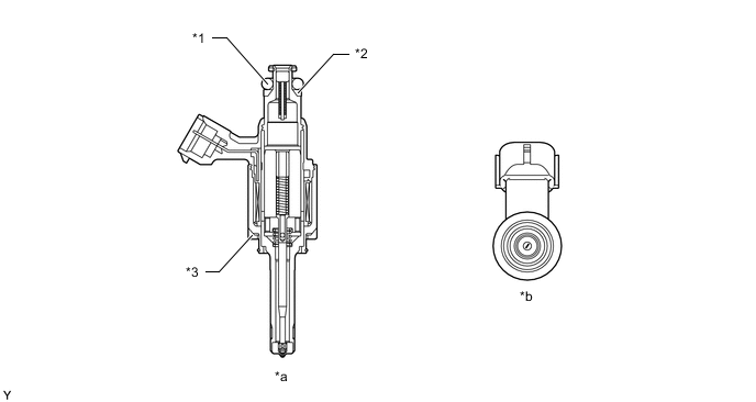
*1 O-ring *2 Backup Ring *3 Insulator - - *a Fuel Injector Assembly (for Direct Injection) Cross Section *b Injection Hole
-