FUEL SYSTEM
-
CONSTRUCTION
-
The fuel in the fuel tank assembly sent by the fuel pump is pressurized in response to driving conditions to a maximum 20 MPa, and the quantity required by the injector is sent to the delivery pipe.
-
The intake valve, discharge valve and relief valve are positioned in series to give the pressurization chamber a compact design, improving discharge efficiency and reducing weight, ultimately leading to improved fuel economy.
-
A fuel pressure pulsation damper is installed inside the fuel pump assembly (for high pressure).
-
An integrated structure is used for the lifter guide and pump housing, achieving high rigidity to improve quietness.
-
The intake valve has been optimized while reducing electromagnetic valve vibrations, enhancing quietness.
-
A roller lifter (fuel pump lifter assembly) is used to drive the plunger. As a result, high engine output and high fuel pressure are supported.
-
The fuel pump assembly (for high pressure) is installed to the camshaft bearing cap via the cylinder head cover sub-assembly and is driven by the cam installed to the exhaust camshaft (No. 2 camshaft).
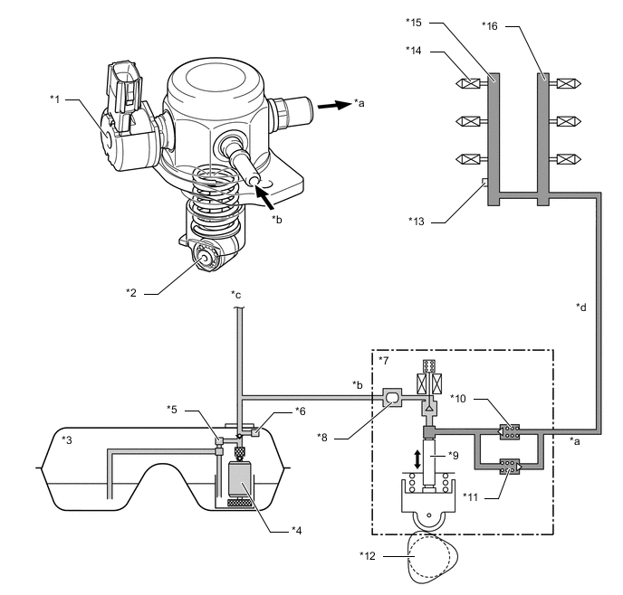
*1 Spill Control Valve *2 Roller Lifter (Fuel Pump Lifter Assembly) *3 Fuel Tank Assembly *4 Fuel Pump (for Low Pressure) *5 Fuel Main Valve Assembly (for Low Pressure) *6 Fuel Main Valve Assembly (for High Pressure) *7 Fuel Pump Assembly (for High Pressure) *8 Fuel Pressure Pulsation Damper *9 Plunger *10 Check Valve *11 Relief Valve *12 Camshaft (Cam to Drive Fuel Pump Assembly (for High Pressure)) *13 Fuel Pressure Sensor (for High pressure) *14 Fuel Injector Assembly (for Direct Injection) *15 Fuel Delivery Pipe with Sensor Assembly LH (for Direct Injection) *16 Fuel Delivery Pipe RH (for Direct Injection) *a High-pressure Fuel System (to Fuel Delivery Pipe (for Direct Injection)) *b Low-pressure Fuel System (from Fuel Tank Assembly) *c To Fuel Delivery Pipe with Sensor Assembly (for Port Injection) *d Pipe of High-pressure Fuel System
-
-
OPERATION
-
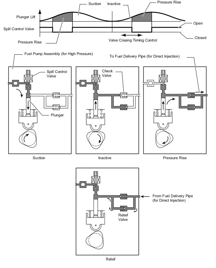
The plunger moves vertically to pressurize the fuel. The fuel is controlled to the necessary fuel pressure by closing the spill control valve, which is installed on the suction side of the fuel pump assembly (for high pressure), at the optimal timing during the compression stroke. When the spill control valve closes at an early timing, the effective stroke of the plunger becomes longer, increasing the fuel pressure.
-
The fuel, which is pressurized by the plunger and controlled to between 2.4 and 20 MPa, pushes open the check valve and is pressure-fed to the fuel delivery pipe (for direct injection).
-
The fuel pressure is detected by the fuel pressure sensor installed in the fuel delivery pipe (for direct injection) and feedback control is performed by the ECM to control the fuel pressure to the target value.
-
When a fuel pressure becomes too high in the high-pressure fuel system, the relief valve opens to leak fuel and suppress the fuel pressure to or below the rated working pressure of the system.
-