ENGINE UNIT
-
CONSTRUCTION
-
The cylinder block sub-assembly is made of aluminum alloy, thus making it lightweight.
-
The cylinder block sub-assembly has a bank angle of 60°, a bank offset of 36.6 mm (1.44 in.) and a bore pitch of 105.5 mm (4.15 in.), resulting in a compact block (length and width) for its displacement.
-
Installation bosses for the 2 knock control sensors are located on the inside of the left and right banks.
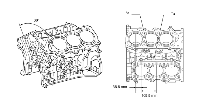
*a Knock Control Sensor Boss - - -
A water passage has been provided between the cylinder bores. By allowing the engine coolant to flow between the cylinder bores, this construction enables the temperature of the cylinder walls to be kept uniform.
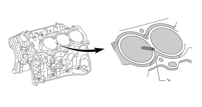
*a Water Passage - - -
A compact block has been achieved by producing the thin cast-iron liners and cylinder block sub-assembly as a unit. It is not possible to rebore a block which uses this type of liner.
-
The liners are a spiny-type, which have been manufactured so that their casting exterior forms a large irregular surface in order to enhance the adhesion between the liners and the aluminum cylinder block sub-assembly. The enhanced adhesion helps improve heat dissipation, resulting in a lower overall temperature and reduced heat deformation of the cylinder bores.
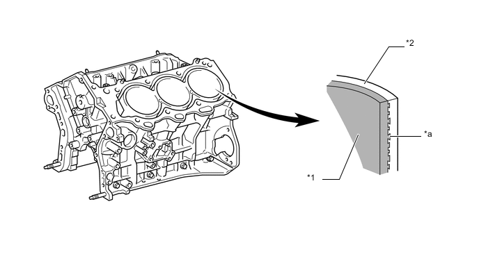
*1 Liner *2 Cylinder Block Sub-assembly *a Irregularly Shaped Outer Casting Surface of Liner - -
-