ENGINE UNIT
-
CONSTRUCTION
-
A 3-blade vane type VVT-iW controller (camshaft timing gear assembly) is used on the intake side.
-
2 lock pins are used to lock the vane during the VVT-iW operation range.
-
An assist spring, which assists torque in the advanced direction, is used so that the vane returns in response the intake camshaft (camshaft) torque fluctuations to securely connect the 2 lock pins. As a result, engine startability is ensured when starting the engine (when cranking) after the engine was stopped in the retarded operation state.
-
An oil control valve is built into the camshaft timing gear bolt, which secures the vane to the intake camshaft (camshaft). As a result, the controlled oil passage is shortened to improve response performance and operation at low temperatures. The oil control valve switches the oil passage when pressed by the cam timing oil control solenoid assembly. Oil passage switching is controlled to continuously change the intake camshaft (camshaft) phase.
-
The oil control valve has a structure which allows independent control of when the 2 lock pins are connected and released, separate from the advance control and retard control.
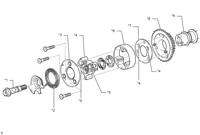
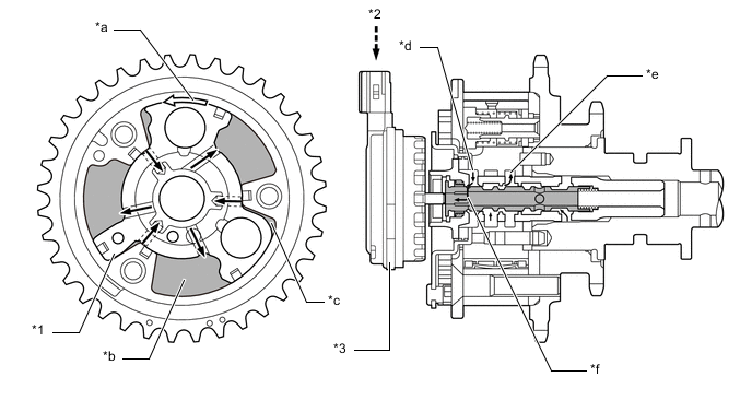
*1 Camshaft Timing Gear Bolt *2 Assist Spring *3 Camshaft Timing Gear Cover FR *4 Vane (Fixed on Intake Camshaft) *5 Lock Pin *6 Housing *7 Camshaft Timing Gear Cover RR *8 Sprocket *9 Intake Camshaft - - *a Ratchet Groove - - Figure 1. Lock Pin
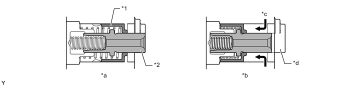
*1 Outer Pin *2 Inner Pin *a Lock Pin Connected *b Lock Pin Released *c Engine Oil *d Ratchet Groove Figure 2. Camshaft Timing Gear Bolt (Built into Oil Control Valve)
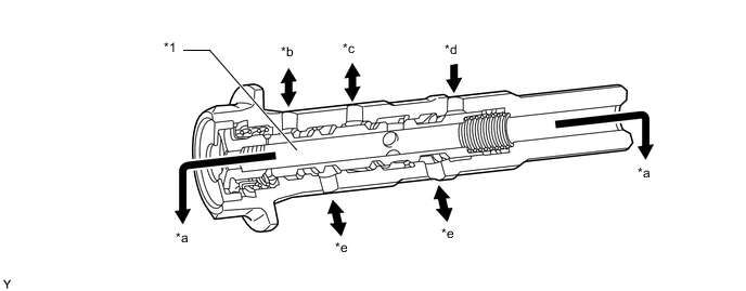
*1 Oil Control Valve - - *a Drain *b To Advance Side Vane Chamber *c To Retard Side Vane Chamber *d Engine Oil *e To Lock Pin - -
-
-
OPERATION
-
Advance
-
The cam timing oil control solenoid assembly operates according to the advance signal from the ECM. When the oil control valve reaches the position shown in the following illustration, the advance side vane chamber of the VVT-iW controller (camshaft timing gear assembly) is affected by oil pressure and the vane inside the VVT-iW controller (camshaft timing gear assembly) rotates in the advanced direction. The intake camshaft (camshaft) fixed to the vane also rotates to the advanced side.
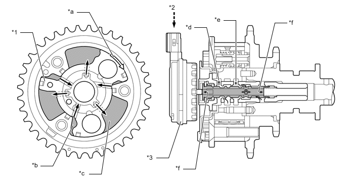
*1 Vane *2 ECM *3 Cam Timing Oil Control Solenoid Assembly - - *a Rotation Direction *b Retard Side Vane Chamber *c Advance Side Vane Chamber *d To Advance Side Vane Chamber *e From Retard Side Vane Chamber *f Drain
-
-
Retard
-
The cam timing oil control solenoid assembly operates according to the retard signal from the ECM. When the oil control valve reaches the position shown in the following illustration, the retard side vane chamber of the VVT-iW controller (camshaft timing gear assembly) is affected by oil pressure and the vane inside the VVT-iW controller (camshaft timing gear assembly) rotates in the retarded direction. The intake camshaft (camshaft) fixed to the vane also rotates to the retarded side.
*1 Vane *2 ECM *3 Cam Timing Oil Control Solenoid Assembly - - *a Rotation Direction *b Retard Side Vane Chamber *c Advance Side Vane Chamber *d From Advance Side Vane Chamber *e To Retard Side Vane Chamber *f Drain
-
-
Hold
-
The ECM calculates the target advanced angle according to driving conditions and performs control. After setting the target timing, timings are maintained by the neutral oil control valve as long as driving conditions do not change. As a result, unnecessary engine oil discharge is suppressed while valve timings are aligned to the desired target position.
-
-