BODY STRUCTURE
-
CONSTRUCTION
-
The edges of the cowl top panel outer (*1 in illustration) have been straightened and the rigidity of the left and right sides have been improved by making the cowl top panel outer (*1 in illustration) which connects the left and right sides a closed cross-section (*a in illustration). Furthermore, by using thick plate for the cowl body mounting reinforcement LH (*3 in illustration) and cowl body mounting reinforcement RH (*4 in illustration) which connect the front suspension tower (*2 in illustration) and cowl top panel outer (*1 in illustration), the rigidity of the connection is improved and superior stability is achieved.
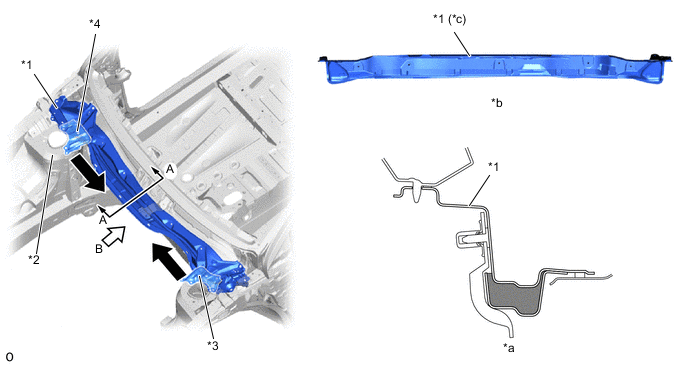
*1 Cowl Top Panel Outer *2 Front Suspension Tower *3 Cowl Body Mounting Reinforcement LH *4 Cowl Body Mounting Reinforcement RH *a A - A Cross Section *b B View *c Straightened Edge - - 
Closed Cross Section - - -
A performance rod (*2 in illustration) is provided inside the cowl top panel outer (*3 in illustration) in the front of the vehicle to help improve body rigidity and achieve excellent stability.
-
Performance dampers (suspension tower damper (*1 in illustration)) are provided inside the front and rear of the vehicle (front: inside the cowl top panel outer (*3 in illustration), rear: inside the body lower back panel (*4 in illustration)) depending on the specifications. The combination of the vehicle's vibration dampening performance with improvements to the body rigidity made by the performance dampers achieves excellent driveability.
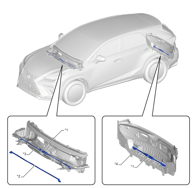
*1 Performance Dampers (Suspension Tower Damper) *2 Performance Rod *3 Cowl Top Panel Outer *4 Body Lower Back Panel -
The addition of adhesive, laser welding (LSW: Laser Spot Welding) and an increased number of spot welding points has increased the connecting ability of the panels to ensure excellent driving stability (steering response and hand feedback).
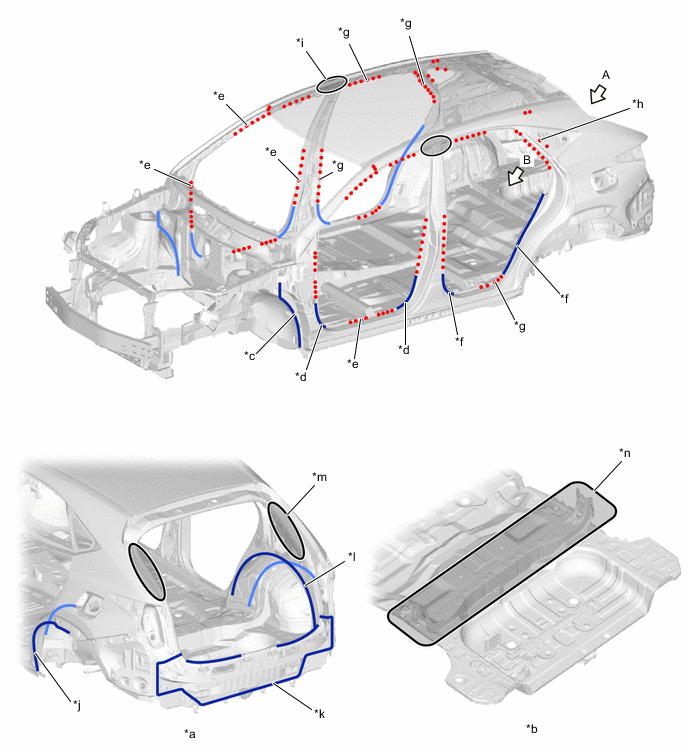
*a A View *b B View *c Front Body Pillar X Dash Panel (Adhered) *d Front Door Opening (Adhered) *e Front Door Opening (LSW) *f Rear Door Opening (Adhered) *g Rear Door Opening (LSW) *h Quarter Opening (LSW) *i Body Center Pillar Outer X Rail Outer (Increased Number of Spot Welding Points) *j Wheelhouse Outer X Side Outer (Adhered) *k Lower Back X Rear Floor (Adhered) *l Wheelhouse Outer X Side Inner (Adhered) *m Backdoor Opening (Increased Number of Spot Welding Points) *n Rear Floor (Increased Number of Spot Welding Points) -
A high-rigidity urethane sealant is used to adhere the windshield glass to the vehicle to improve body rigidity and ensure excellent driving stability.
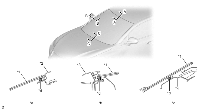
*1 Windshield Glass *2 Roof Panel *3 Side Panel Outer *4 Cowl Top Panel Outer *a A - A Cross Section *b B - B Cross Section *c C - C Cross Section *d High-rigidity Urethane Sealant -
The rigidity of parts around the front suspension crossmember sub-assembly has been increased and airfoil cross-section shapes have been added to improve airflow under the floor and ensure driving stability.
-
Closed cross-section of front suspension member reinforcement RH and LH (*1 and *3 in illustration)
-
Closed cross-section of radiator support lower (*2 in illustration)
-
Unified large-size front suspension member brace (*4 in illustration)
-
Airfoil cross-section shape added to front floor cover RH (*6 in illustration), front floor cover (*10 in illustration) and rear floor side member cover (*8 in illustration)
-
Stabilizer bar rear (*7 in illustration) provided
-
Unified left and right braces of rear suspension brace sub-assembly (*9 in illustration)
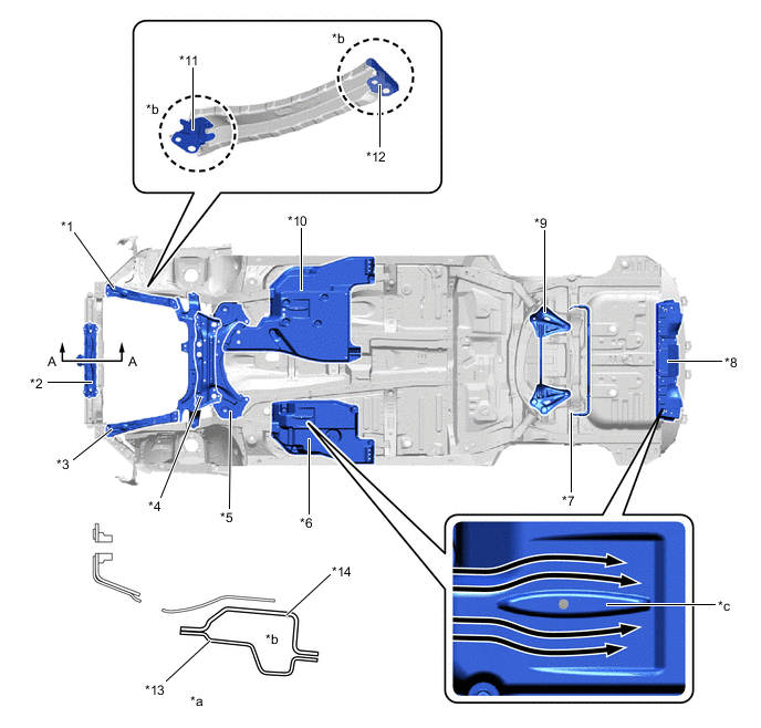
*1 Front Suspension Member Reinforcement RH *2 Radiator Support Lower *3 Front Suspension Member Reinforcement LH *4 Front Suspension Member Brace *5 Front Suspension Crossmember Sub-assembly *6 Front Floor Cover RH *7 Stabilizer Bar Rear *8 Rear Floor Side Member Cover *9 Rear Suspension Brace Sub-assembly *10 Front Floor Cover *11 Side Rail Reinforcement LWR RH No.4 *12 Side Rail Extension Reinforcement No. 1 *13 Radiator Support Lwr Rear *14 Radiator Support Lower *a A - A Cross Section *b Made a Closed Cross-section *c Airfoil Cross-section Shape - - 
Airflow - -
-
-