BODY STRUCTURE
-
CONSTRUCTION
-
Impact Absorbing Structure for Frontal Collision
-
A structure that ensures collision energy absorption efficiency, dissipates impact and minimizes cabin deformation during a frontal collision has been achieved.
-
A structure which dissipates impact load from the front side member sub-assembly (*3 in illustration) through the torque box front (*5 in illustration) to the rocker portion (*7 in illustration) is used.
-
A structure which dissipates impact load from the front apron to cowl side member sub-assembly (*4 in illustration) through the front body pillar portion (*9 in illustration) to the rail portion (*10 in illustration) is used.
-
A structure which dissipates impact load from the front apron to cowl side member sub-assembly (*4 in illustration) through the MICS bulkhead (cowl top side panel (*6 in illustration)) to the access panel instrument panel reinforcement sub-assembly (*8 in illustration) is used.
Tech Tips
*: MICS: Minimum Intrusion Cabin System
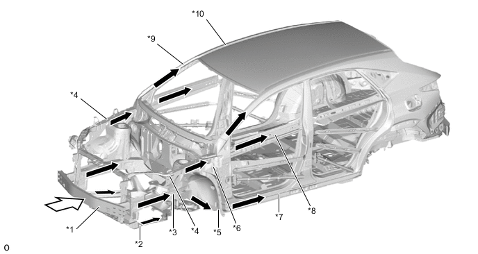
*1 Front Bumper Reinforcement Sub-assembly *2 Front Cross Member Sub-assembly *3 Front Side Member Sub-assembly *4 Front Apron to Cowl Side Member Sub-assembly *5 Torque Box Front *6 Cowl Top Side Panel *7 Rocker Portion *8 Access Panel Instrument Panel Reinforcement Sub-assembly *9 Front Body Pillar Portion *10 Rail Portion 
Front Impact Energy 
Dissipate -
A structure which dissipates impact load from the front apron to cowl side member sub-assembly (*1 in illustration) through the under body frameworks is used.
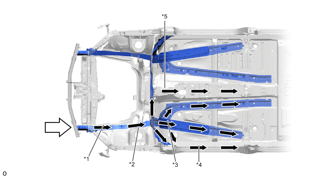
*1 Front Apron To Cowl Side Member Sub-assembly *2 Dash Panel *3 Front Floor Side Panel Sub-assembly *4 Rocker Portion *5 Front Floor Panel Sub-assembly Ctr - - Front Impact Energy Dissipate
-
-
-
Impact Absorbing Structure for Side Collision
-
A structure that ensures collision energy absorption efficiency, dissipates impact and minimizes cabin deformation during a side collision has been achieved.
-
Ultra high strength sheet steel (tensile strength: 980 MPa class) is used for the rocker reinforcement outer (*7 in illustration) and center pillar upper hinge reinforcement No. 1 (*3 in illustration). Hot-stamped steel (tensile strength: 1500 MPa class) is used for the roof side rail (*1 in illustration). High strength sheet steel (tensile strength: 590 MPa class) is used for the roof panel side strength No. 1 (*12 in illustration), etc. Tailor welded blanks (tensile strength: 590 MPa class (*4 in illustration), 980 MPa class (*5 in illustration) and 440 MPa class (*6 in illustration) are used for the center body pillar reinforcement outer (*4, *5 and *6 in illustration).
*: Tailor welded blanks are pieces of steel that have been laser welded in advance.
-
A structure which uses the floor side member reinforcement No. 1 (*13 in illustration) and front floor panel side plate (*14 in illustration) in the rocker and under body under the center body pillar to efficiently transmit impact load during a side collision to the floor is used.
-
A structure which optimizes the placement of the rear door protection beam sub-assembly to efficiently transmit impact load is used.
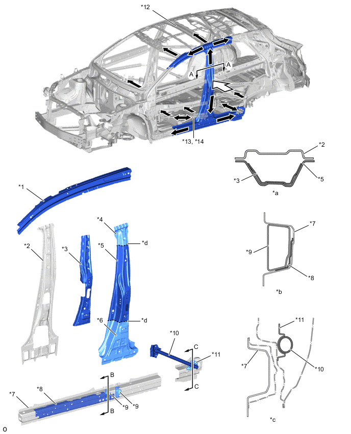
*1 Roof Side Rail (Tensile Strength: 1500 MPa class) *2 Center Body Pillar Inner Upper (Tensile Strength: 590 MPa class) *3 Center Pillar Upper Hinge Reinforcement No. 1 (Tensile Strength: 980 MPa class) *4 Center Body Pillar Reinforcement Outer (Tensile Strength: 590 MPa class) *5 Center Body Pillar Reinforcement Outer (Tensile Strength: 980 MPa class) *6 Center Body Pillar Reinforcement Outer (Tensile Strength: 440 MPa class) *7 Rocker Reinforcement Outer (Tensile Strength: 980 MPa class) *8 Front Step Retainer (Tensile Strength: 980 MPa class) *9 Rocker Panel Reinforcement No. 4 (Tensile Strength: 440 MPa class) *10 Rear Door Protection Beam Sub-assembly *11 Rear Door Beam Extension Rear (Tensile Strength: 440 MPa class) *12 Roof Panel Side Strength No. 1 (Tensile Strength: 590 MPa class) *13 Floor Side Member Reinforcement No. 1 *14 Front Floor Panel Side Plate *a A - A Cross Section *b B - B Cross Section *c C - C Cross Section *d Tailored Blank Line Side Impact Energy Dissipate
-
-
-
Impact Absorbing Structure for Rear Collision
-
A structure that ensures collision energy absorption efficiency, dissipates impact and minimizes cabin deformation during a rear collision has been achieved.
-
The large-size rear bumper reinforcement No. 1 is used to dissipate the impact load during a rear offset collision. The rear bumper reinforcement No. 1 dissipates impact load to the left and right members to suppress deformation of the cabin.
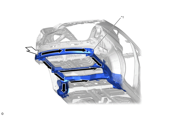
*1 Rear Bumper Reinforcement No. 1 - - Rear Impact Energy Dissipate
-
-
-
Other Occupant Protection Device
-
The glove compartment door assembly has been strengthened to secure the legs of the occupant during an impact and reduce the impact to the occupant.
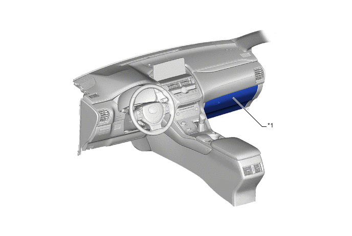
*1 Glove Compartment Door Assembly - - -
An impact load absorbing structure is used which ensures an impact reducing area for when an occupant's head, etc., impacts the pillar and roof side due to a collision. Energy absorbing pads are provided inside the garnish, which a rib structure, and the roof headlining assembly. The pads collapse during a collision to reduce the impact to the occupant's head, etc.
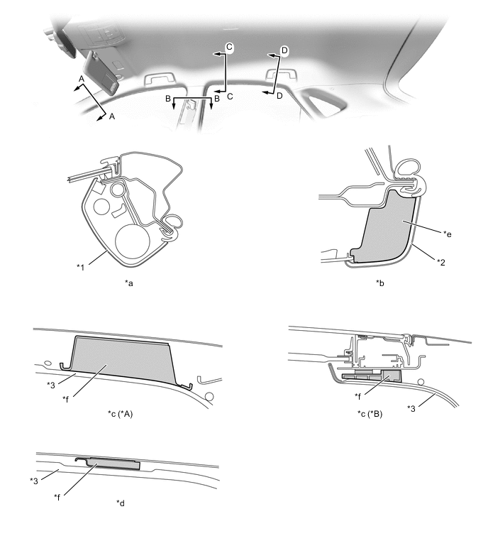
*A Models with Normal Roof *B Models with Sliding Roof *1 Front Pillar Garnish Assembly *2 Center Pillar Garnish Assembly *3 Roof Headlining Assembly - - *a A - A Cross Section *b B - B Cross Section *c C - C Cross Section *d D - D Cross Section *e Energy Absorbing Rib *f Energy Absorbing Pad -
The front door trim pad and door trim pad LWR are provided at waist-height in the front door trim and rear door trim to reduce the impact to the occupant during a side collision.
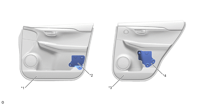
*1 Front Door Trim Board Sub-assembly *2 Front Door Trim Pad *3 Rear Door Trim Board Sub-assembly *4 Door Trim Pad LWR
-
-
Reduction Pedestrian Head Injury
-
The following shape is used for around the front body, thus maintaining necessary rigidity and aiming for a reduction of impact against a pedestrian in a collision with a pedestrian.
-
The hood panel (*2 in illustration) uses a structure which ensures an impact absorption stroke at the front between the hood lock hook (*5 in illustration) and hood inner panel reinforcement (*6 in illustration) in order to reduce the impact to the pedestrian whose head and legs struck the hood.
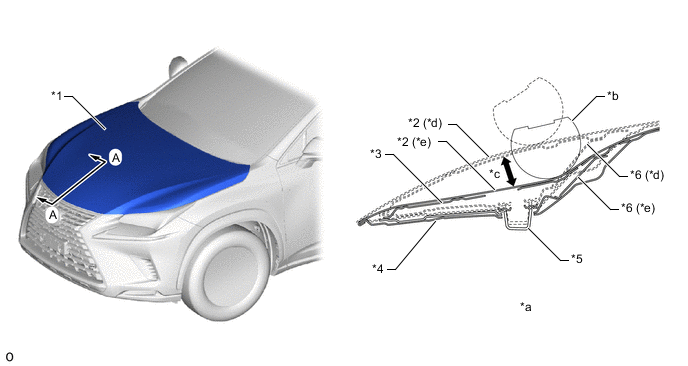
*1 Hood Sub-assembly *2 Hood Panel *3 Hood Panel Reinforcement *4 Hood Lock Hook Reinforcement *5 Hood Lock Hook *6 Hood Inner Panel Reinforcement *7 Hood Panel Inner - - *a A - A Cross Section *b Head Form *c Impact Absorption Stroke *d Before Collision *e After Impact Absorption -
The parts surrounding the cowl top ventilator louver sub-assembly (*1 in illustration) use a crushable structure to improve the rate of energy absorption from the estimated collision direction to reduce the impact to the pedestrian whose head, etc., struck the area. The structure of the cowl top ventilator louver sub-assembly (*1 in illustration) maintains the necessary rigidity while having a lowered deformation strength in order to absorb impact load. Also, the cowl top to cowl brace inner No. 1 (*6 in illustration) and cowl top panel inner (*7 in illustration) collapse similar to a pantograph in order to absorb impact load.
-
During a collision, a falling stroke for the front wiper motor and link assembly (*8 in illustration) is ensured in consideration of reducing damage by preventing the front wiper motor and link assembly (*8 in illustration) from striking the bottom.
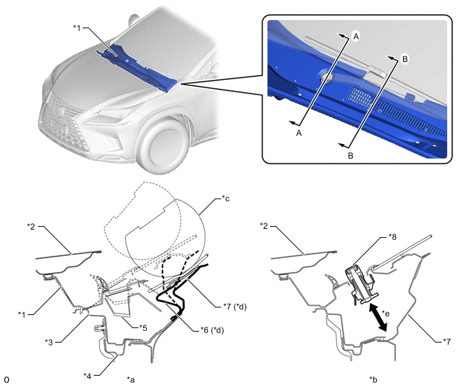
*1 Cowl Top Ventilator Louver Sub-assembly *2 Hood Sub-assembly *3 Cowl Top Panel Outer Front *4 Cowl Top Rail Outer *5 Cowl Vent Splash Shield *6 Cowl Top To Cowl Brace Inner No. 1 *7 Cowl Top Panel Inner *8 Front Wiper Motor And Link Assembly *a A - A Cross Section *b B - B Cross Section *c Head Form *d Structure Collapses Similar to Pantograph *e Falling Stroke - - -
An impact absorption bracket (apron fender side extension (*1 in illustration) and front fender apron extension rear (*2 in illustration)) are provided around the front fender apron sub-assembly (*3 in illustration) to absorb impact load during a collision and collapse, forming a structure which reduces the impact to the pedestrian whose head, etc., struck the fender.
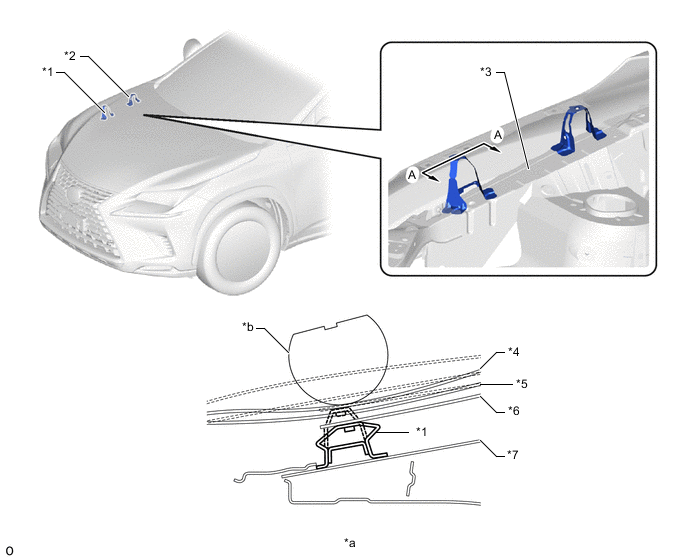
*1 Apron Fender Side Extension *2 Front Fender Apron Extension Rear *3 Front Fender Apron Sub-assembly *4 Hood Panel *5 Hood Panel Inner *6 Front Fender Sub-assembly *7 Fender Side Apron Sub-assembly - - *a A - A Cross Section *b Head Form
-
-
-
Reduction Pedestrian Leg Injury
-
A pedestrian injury reduction body is used in consideration of reducing injury of a pedestrian in the case of a collision with a pedestrian. The impact absorbing structure is used on the periphery of the front bumper, thus achieving a body structure which reduces impact on pedestrian's legs, etc.
-
A front bumper energy absorber (*1 in illustration) is provided in front of the front bumper reinforcement sub-assembly (*4 in illustration) and a front bumper absorber lower made of resin (*2 in illustration) is provided under the radiator grille to form a structure which reduces the impact to the pedestrian whose lower leg struck the bumper.
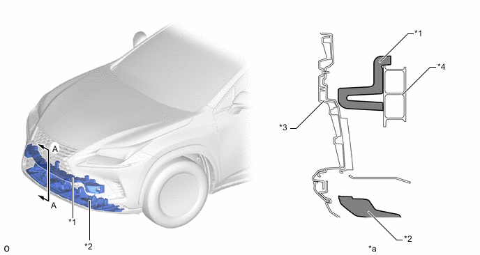
*1 Front Bumper Energy Absorber *2 Front Bumper Absorber Lower *3 Front Bumper Cover *4 Front Bumper Reinforcement Sub-assembly *a A - A Cross Section - -
-
-
-