AIR CONDITIONING SYSTEM
-
CONSTRUCTION
-
An air conditioning unit that is compatible with left and right independent temperature control is used.
-
A partial recirculation structure that circulates a portion of the air in the cabin when in fresh air mode is used in an effort to improve heater performance.
-
A Beneficial Refrigerant Stream (BRS) type evaporator is used.
-
A Straight Flow Aluminum-II (SFA-II) heater core that is compact and offers advanced performance is used.
-
A compact wide-angle high flow defroster that gives the defroster nozzle assembly inner wall a radial shape is used to ensure superior defroster performance.
-
A pollen and odor-removing type clean air filter (air refiner element) is provided as standard equipment.
Figure 1. Air Conditioning Unit Layout Parts Location
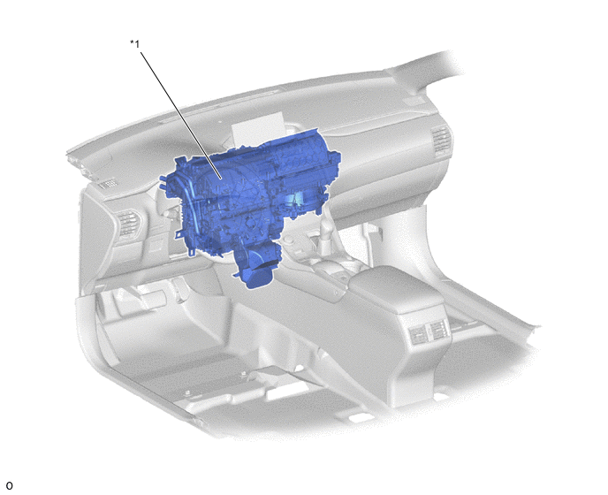
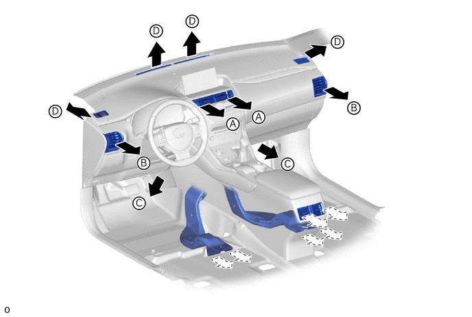
*1 Air Conditioning Unit Assembly - - Figure 2. Duct Layout Parts Location
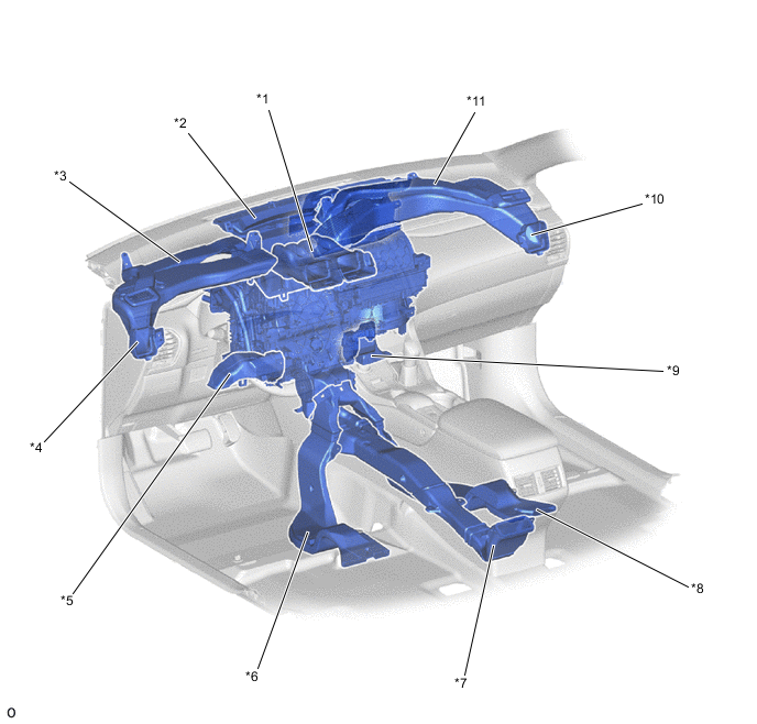
*1 Center Register Duct *2 Front Defroster Duct *3 Driver Side Defroster Duct *4 Driver Side Register Duct *5 Driver Side Footwell Register Duct *6 Driver Side Rear Footwell Register Duct *7 Console Rear Face Register Duct *8 Front Passenger Side Rear Footwell Register Duct *9 Front Passenger Side Footwell Register Duct *10 Front Passenger Side Register Duct *11 Front Passenger Side Defroster Duct - -
-
-
OPERATION
-
Mode Position and Damper Operation
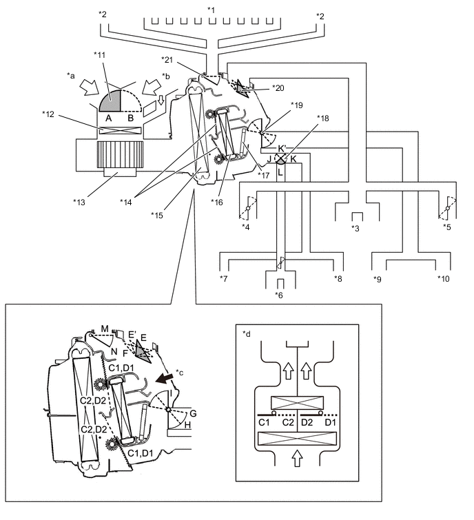
*1 Front Defroster *2 Side Defroster *3 Center Register *4 Driver Side Side Register *5 Front Passenger Side Side Register *6 Console Rear Face Register *7 Driver Side Rear Footwell Register *8 Front Passenger Side Rear Footwell Register *9 Driver Side Footwell Register *10 Front Passenger Side Footwell Register *11 Air Inlet Control Door *12 Clean Air Filter (Air Refiner Element) *13 Blower Motor with Fan Assembly *14 Air Mix Control Door *15 No. 1 Cooler Evaporator Sub-assembly *16 Air Conditioning Radiator Sub-assembly *17 PTC Heater (Quick Heater Assembly) *18 Mode Switching Door for Rear Register *19 Mode Switching Door for Front Footwell Register *20 Mode Switching Door for Front Register *21 Mode Switching Door for Front and Side Defroster - - *a Fresh Air *b Recirculated Air *c [A] View *d Illustration Image View from [A] Mode Position and Door Operation Control Door Operation Position Door Position Operation Air Inlet Control Door FRESH B Brings in fresh air. RECIRCULATION A Recirculates internal air. Air Mix Control Door HI - LO C1 - C2 Varies the driver side mixture ratio of the hot air and the cool air in order to regulate the temperature continuously from HI to LO. D1 - D2 Varies the front passenger side mixture ratio of the hot air and the cool air in order to regulate the temperature continuously from HI to LO. Mode Control Door (for All Seat Control Mode) FACE E, I, K, M Air blows out of the front center register, side register and console rear face register. BI-LEVEL E', H, K', M Air blows out of the front center register, side register, console rear face register and front and rear footwell register ducts. FOOT F, G, L, N Air blows out of the front footwell register, rear footwell register and front register ducts. In addition, air blows out slightly from the front defroster, side defroster and console rear face register. FOOT/DEF F, H, L, N Defrosts the windshield through the front defroster. At the same time, air is blown out from the footwell register and rear footwell register. A small amount of air also blows out from the side register and console rear face register. DEF F, I, J, N Defrosts the windshield through the front defroster and side defroster. A small amount of air also blows out from the side register. Mode Control Door (for Front Seat Control Mode) FACE E, I, J, M Air blows out of the front center register and side register. BI-LEVEL E', H, J, M Air blows out of the front center register, side register and front footwell register ducts. FOOT F, G, J, N Air blows out of the front footwell register and front side register ducts. In addition, air blows out slightly from the front defroster and side defroster. FOOT/DEF F, H, J, N Defrosts the windshield through the front defroster. At the same time, air is blown out from the front footwell register. A small amount of air also blows out from the side register. -
Air Outlets and Airflow Volume (for All Seat Control Modes)
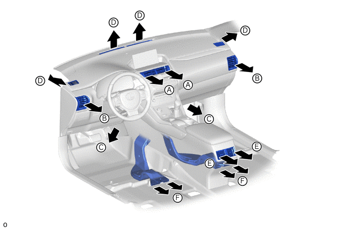
MODE A B C D E F Center Register Side Register Front Footwell Defroster Console Rear Face Register Rear Footwell 
FACE 
- - - 
BI-LEVEL 
- 
FOOT - 

FOOT/DEF - 
DEF - - - - -
Air Outlets and Airflow Volume (for Front Seat Control Modes)
MODE A B C D E F Center Register Side Register Front Footwell Defroster Console Rear Face Register Rear Footwell FACE - - - - BI-LEVEL - - - FOOT - - - FOOT/DEF - - -
-