NAVIGATION SYSTEM / MULTI INFORMATION SYSTEM
-
CONSTRUCTION
-
By using the remote touch, screen operations can be performed within reach of the user. Together with installing the multi-display in an easily visible position that minimizes the distance that drivers have to move their eyes, this helps reduce the operational burden while increasing the visibility of the screen.
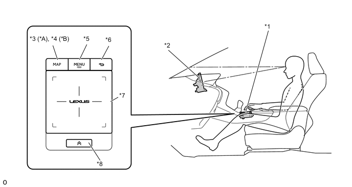
*A Models with Navigation System *B Except Models with Navigation System *1 Remote Touch (Remote Operation Controller Assembly) *2 Multi-display *3 MAP Switch *4 HOME Switch *5 MENU Switch *6 BACK Switch *7 Touch Pad *8 Sub-function Switch -
The remote touch generates touch pad vibrations with an internal motor according to changes in the selection buttons in order to provide feedback to the user's hand. This feedback supports selecting buttons on the screen, achieving improvements in operability.
-
A stabilizer structure is used to ensure that the pad does not tilt and operations are recognized no matter where the touch pad is pressed.
-
An electrostatic type touch pad is used. The electrostatic detection area of the touch pad is as follows.
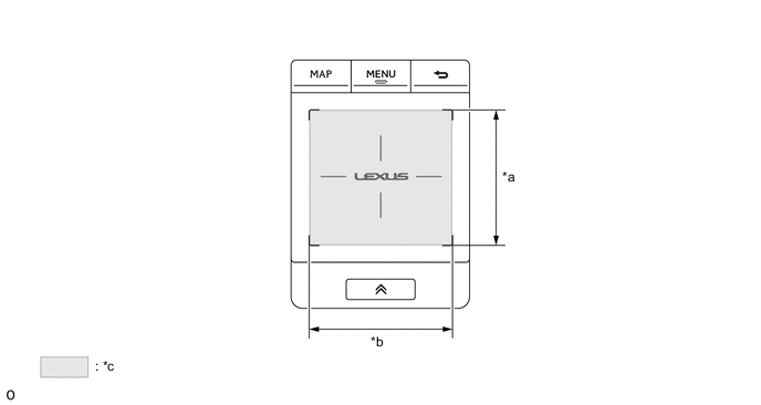
*a 62 mm (2.44 in.) *b 65 mm (2.55 in.) *c Detection Area - - -
The touch pad has two axes, a horizontal axis (x-axis) and a vertical axis (y-axis), which each has position coordinates that range from 0 to 255. The detected position coordinates are sent to the navigation ECU.
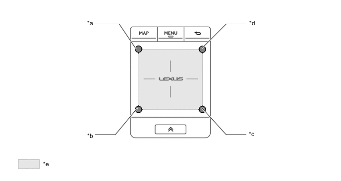
*a (X, Y) = (0, 0) *b (X, Y) = (0, 255) *c (X, Y) = (255, 255) *d (X, Y) = (255, 0) *e Detection Area - - -
The touch pad uses the following detection items to detect contact by a single finger or multiple fingers.
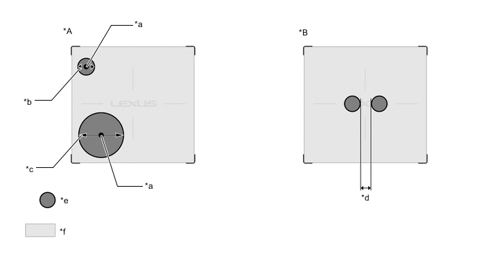
*A Finger Detection/Finger Coordinate Position Detection *B Multiple Finger Detection *a Center Area of Finger Contact Area *b 7.4 mm (0.29 in.) (Minimum Finger Diameter) *c 31.5 mm (1.24 in.) (Maximum Finger Diameter) *d 6 mm (0.23 in.) (Minimum Distance between Fingers) *e Finger Contact Area *f Detection Area Search Item Table Detection Item Details Finger Detection Fingers that are 7.4 mm (0.29 in.) to 31.5 mm (1.24 in.) in diameter can be detected. Anything outside that range will not be detected as a finger. Finger Coordinate Position Detection The coordinates (X coordinates, Y coordinates) of where the touch pad is contacted by a finger are detected by using the center position of the surface where the touch pad is contacted by a finger as the contact position. Multiple Finger Detection When a finger contact position (distance between edges) is 6 mm (0.23 in.) or more from another finger contact position, it is recognized as a separate finger and multiple finger detection occurs. Tech Tips
The values may differ from the ones in the actual vehicle.
-
-
OPERATION
-
Remote Touch Operation
-
Remote touch operations are displayed by the system highlighting the buttons of the multi-display or moving the pointer.
-
When the remote touch is operated, the remote touch calculates the difference based on the previous pointer position coordinates sent to the navigation ECU and sends the result to the navigation ECU.
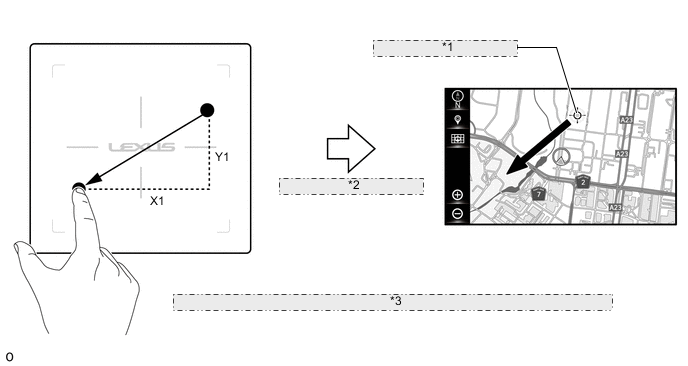
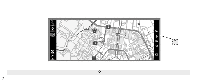
*1 Coordinates as (X0, Y0) *2 Sends New Coordinates as (X0+X1, Y0+Y1) *3 The illustration shown is an example only. The illustration may differ from the actual vehicle screen. -
The multi-display screen has two axes, a horizontal axis and a vertical axis, which each has position coordinates. The navigation ECU displays the pointer or cursor at the display position coordinates according to remote touch operations.
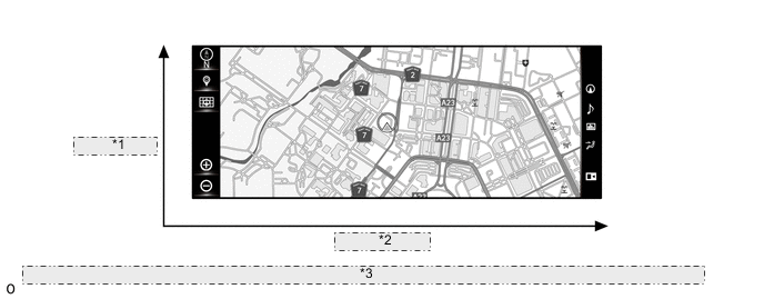
*1 Vertical Axis *2 Horizontal Axis *3 The illustration shown is an example only. The illustration may differ from the actual vehicle screen.
-
-
Vibration Feedback Control
-
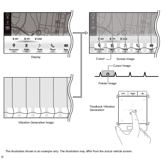
A motor, which generates vibrations on the touch pad according to remote touch operations, is built into the remote touch.
-
The navigation ECU sends screen information corresponding to each screen mode shown on the multi-information to the remote touch.
-
The remote touch controls the built-in motor according to the received screen information to generate vibrations on the touch pad.
-
-
Button Pull-in Control
-
The button that is closest to the current pointer coordinates is judged to be the pull-in button, and the pointer is pulled to the center of that button.
-
When the pull-in button changes as shown in the following illustration, the touch pad of the remote touch vibrates.
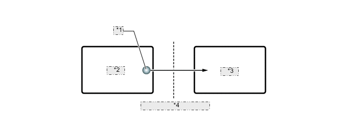
*1 Pointer *2 Icon B *3 Icon A *4 Vibration Generated on Touch Pad
-
-
Frame Area Control
-
A frame area surrounds all screens. The frame area prevents the pointer from moving outside the screen.
*1 Frame Area *2 The illustration shown is an example only. The illustration may differ from the actual vehicle screen.
-
-
Customization
-
A customization function is provided which can be used to change settings according to user preference. For details refer to the Repair Manual.
-
-