POWER STEERING SYSTEM
-
CONSTRUCTION
-
Models with Power Tilt and Telescopic System
-
A Hall IC type power steering torque sensor is used.
-
The power steering torque sensor is built into the steering column assembly. A multipole magnet is mounted on the input shaft, and a yoke is mounted on the output shaft. The input and output shafts are joined by the torsion bar. A magnetic convergence ring assembly is placed outside of the yoke.
-
The magnetic convergence ring assembly contains 2 Hall ICs, which face opposite to each other. The system detects the steering direction in accordance with the direction of the magnetic flux that passes between the Hall ICs. Furthermore, the system detects the steering torque in accordance with the amount of change in the magnetic flux density based on the relative displacement of the multipole magnet and the yoke. The power steering ECU monitors the torque sensor signals output by the 2 Hall ICs to detect malfunctions.
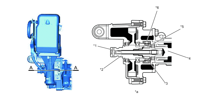
*1 Torsion Bar *2 Output Shaft *3 Yoke *4 Input Shaft *5 Multipole Magnet *6 Magnetic Convergence Ring Assembly *a A-A Cross Section - - 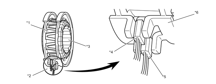
*1 Yoke *2 Power Steering Torque Sensor *3 Multipole Magnet *4 Hall IC 2 *5 Hall IC 1 *6 Magnetic Convergence Ring Assembly Figure 1. Fluctuation of Magnetic Flux Density that Passes through Hall IC
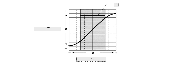
*1 Range of Use *2 Output Voltage (V) *3 Steering Torque (Nm)
-
-
Models with Manual Tilt and Telescopic Mechanism
-
Variable inductance type power steering torque sensor is used.
-
The power steering torque sensor is built into the steering column assembly. The power steering torque sensor consists of a detection ring, a stub shaft and 2 detection coils.
-
The detection ring is mounted on the input shaft and the stub shaft is mounted on the output shaft. The input shaft and the output shaft are joined by the torsion bar. The detection coils are placed on the outside of the detection ring to complete an excitation circuit without making contact.
-
When the steering wheel is turned, the twist that is created in the torsion bar creates a relative displacement between the detection ring and the stub shaft. The torque sensor outputs this change as an electrical signal to the power steering ECU.
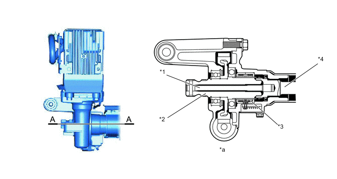
*1 Torsion Bar *2 Output Shaft *3 Power Steering Torque Sensor *4 Input Shaft *a A-A Cross Section - - Figure 2. Power Steering Torque Sensor
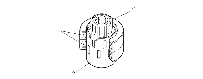
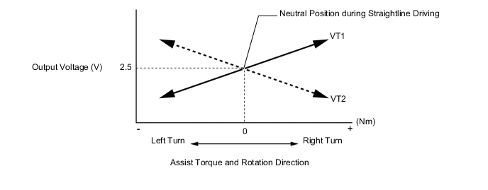
*1 Detection Coil *2 Detection Ring *3 Stub Shaft - - Figure 3. Power Steering Torque Sensor Output Characteristic
-
-