BRAKE SYSTEM
-
CONSTRUCTION
-
Brake Master Cylinder
-
The brake booster with master cylinder assembly consists of the brake master cylinder, brake actuator, brake master stroke simulator cylinder assembly and skid control ECU.
Figure 1. Brake Booster with Master Cylinder Assembly
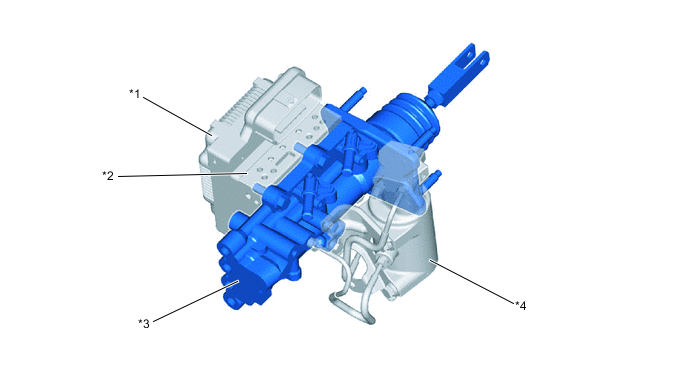
*1 Skid Control ECU *2 Brake Actuator *3 Brake Master Cylinder *4 Brake Master Stroke Simulator Cylinder Assembly -
The brake master cylinder uses a center valve type single master cylinder.
-
The brake master cylinder consists of the operating rod which is directly connected to the brake pedal, power piston, master cylinder piston, regulator piston and spool valve to switch the brake fluid passage.
-
The operating rod is directly connected to the power piston, by which the operating force of the brake pedal is transmitted.
-
The regulator piston is directly connected to the spool valve through which the master cylinder pressure is applied to the regulator piston in the advance direction (from the left in the illustration) and the pressure boosted by the brake booster is applied to the piston in the retard direction (from the right in the illustration), thus balancing the pressures in both directions. In addition, a return spring is placed in the regulator piston to ensure the return force of the spool valve when no pressure is applied.
Figure 2. Brake Master Cylinder Cross Section
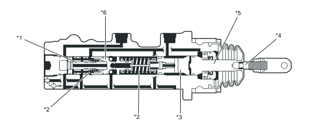
*1 Spool Valve *2 Return Spring *3 Master Cylinder Piston *4 Operating Rod *5 Power Piston *6 Regulator Piston
-
-
-
OPERATION
-
Brake Master Cylinder
-
When the brake pedal is depressed by the driver, the operating force of the brake pedal is transmitted from the operating rod via the power piston to the master cylinder piston. The return spring of the master cylinder chamber has a higher setting load than that of the regulator piston, thus allowing the regulator piston to move forward before the master cylinder chamber is compressed.
-
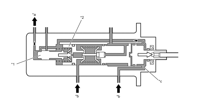
The spool valve closes the oil passage to the brake master cylinder reservoir assembly and the booster chamber and opens the oil passage from the accumulator and the booster chamber. These two operations allow the fluid pressure to be applied to the booster chamber, generating a boosted force and further boosting the brake pedal force. When the fluid pressure is applied to the booster chamber, the boosted force overcomes the return spring force, compressing the master cylinder chamber and increasing the fluid pressure.
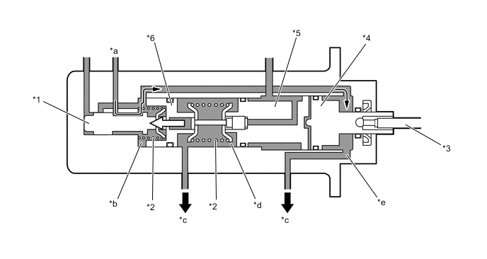
*1 Spool Valve *2 Return Spring *3 Operating Rod *4 Power Piston *5 Master Cylinder Piston *6 Regulator Piston *a From Accumulator *b Regulator Chamber *c To Brake Actuator *d Master Cylinder Chamber *e Booster Chamber - -
When the driver's pedal operation is stopped and the pedal operating force and the master cylinder pressure are balanced, the forces are respectively applied to the front and rear of the regulator piston. In other words, the forces respectively generated by the master cylinder pressure and the regulator pressure are balanced, and as a result the spool valve closes the passage between the booster chamber and the accumulator, and also to the brake master cylinder reservoir assembly.
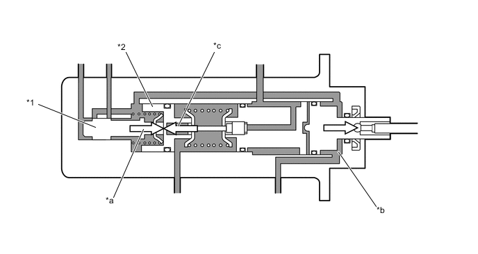
*1 Spool Valve *2 Regulator Piston *a Regulator Pressure *b Booster Chamber *c Master Cylinder Pressure - - -
When the driver's pedal operating force is reduced, the master cylinder pressure drops. As a result, the force applied to the regulator piston return side becomes larger relatively and theregulator piston and the spool valve move further rearward, opening the fluid passage betweenthe brake master cylinder reservoir assembly and the booster chamber.
-
As a result, the brake fluid in the brake master cylinder is returned to the brake master cylinder reservoir assembly, decreasing the booster chamber pressure and balancing the booster chamber pressure against the reduced master cylinder pressure. This repetitive operation decreases the booster chamber pressure and the master cylinder pressure in accordance with the pedal operating force.
*1 Spool Valve *2 Regulator Piston *a To Brake Master Cylinder Reservoir Assembly *b From Brake Actuator *a Booster Chamber - -
-
-