ADAPTIVE VARIABLE SUSPENSION SYSTEM
-
CONSTRUCTION
-
The shock absorber assembly has a absorber control actuator, which changes the damping force, positioned on the lower part of the outer shell.
-
A center pipe is provided to create an oil passage to the absorber control actuator. During bound and rebound, oil flows in the same direction in the center pipe and the damping force is changed within the absorber control actuator.
Figure 1. Shock Absorber Assembly Cross Section
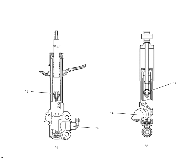
*1 Front Shock Absorber Assembly *2 Rear Shock Absorber Assembly *3 Center Pipe *4 Absorber Control Actuator Figure 2. Oil Flow
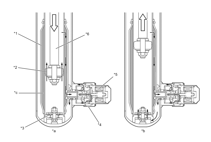
*1 Center Pipe *2 Piston Valve *3 Base Valve *4 Absorber Control Actuator *5 Linear Solenoid *6 Absorber Rod *a During Bound *b During Rebound *c Center Oil Passage - -
-
-
OPERATION
-
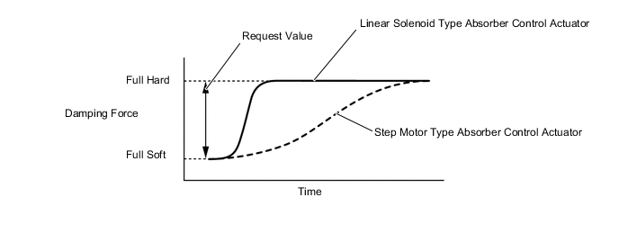
Pilot pressure at the rear of the main valve is controlled to vary the pressure (damping force) that opens the main valve. The pilot pressure is continuously adjusted by the linear solenoid in 650 steps to achieve superior response.
-
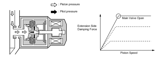
The pilot pressure is determined by the balance between the linear solenoid action and piston pressure. When the linear solenoid action is small (low current), the pilot pressure becomes lower. As a result, the damping force becomes lower. Conversely, when the linear solenoid action is large (high current), the pilot pressure becomes higher. As a result, the damping force becomes higher.
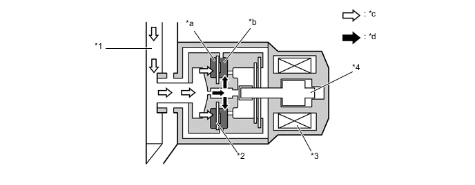
*1 Center Pipe *2 Main Valve *3 Linear Solenoid *4 Spool Valve *a Piston Pressure Chamber *b Pilot Pressure Chamber *c Piston Pressure *d Pilot Pressure Figure 3. Absorber Control Actuator Operation (Low Damping Force)
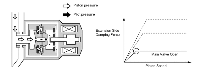
Figure 4. Absorber Control Actuator Operation (High Damping Force)
-