ENGINE UNIT
-
CONSTRUCTION
-
The cylinder block sub-assembly is made of aluminum alloy, so it is lightweight.
-
Water passages are provided between the cylinder bores. By allowing the engine coolant to flow between the cylinder bores, this construction enables the temperature of the cylinder walls to be kept uniform.
-
The liners are the spiny-type, which have been manufactured so that their casting exteriors form large irregular surfaces in order to enhance the adhesion between the liners and the aluminum cylinder block. The enhanced adhesion helps heat dissipation, resulting in a lower overall temperature and heat deformation of the cylinder bores.
-
An oil separator is provided in the blowby gas passage inside the cylinder block. This separates the engine oil from the blowby gas in order to reduce the degradation and consumption of engine oil.
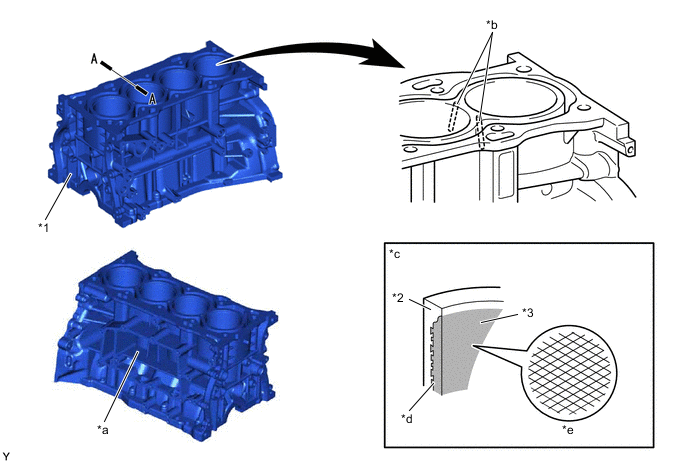
*1 Cylinder Block Assembly *2 Cylinder Bore *3 Cylinder Liner - - *a Oil Separator *b Water Passage *c A - A Cross Section *d Spiny-type Liner *e Bore Cross Hatching - - -
Through the use of the offset crankshaft, the bore center is shifted 10 mm (0.39 in.) towards the exhaust, in relation to the crankshaft center. Thus, the side force to the cylinder wall is reduced when the maximum pressure is applied, which contributes to fuel economy.
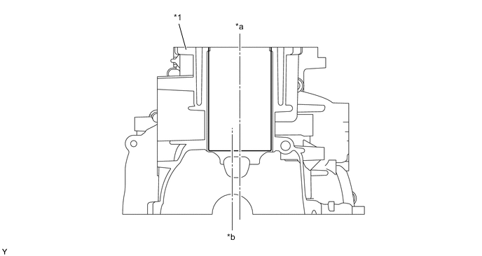
*1 Cylinder Block Sub-assembly - - *a Bore Center *b Crankshaft Center -
A shallow bottom water jacket is used. The resulting reduction in the volume of the engine coolant improves warm-up performance, which contributes to improved fuel economy.
-
A water jacket spacer is provided in the water jacket of the cylinder block sub-assembly.
-
The water jacket spacer suppresses the water flow in the bottom of the water jackets, guides the coolant in the upper area of the water jacket, and ensures uniform temperature distribution. As a result, the viscosity of the engine oil that acts as a lubricant between the bore walls and the pistons can be lowered, thus reducing friction.
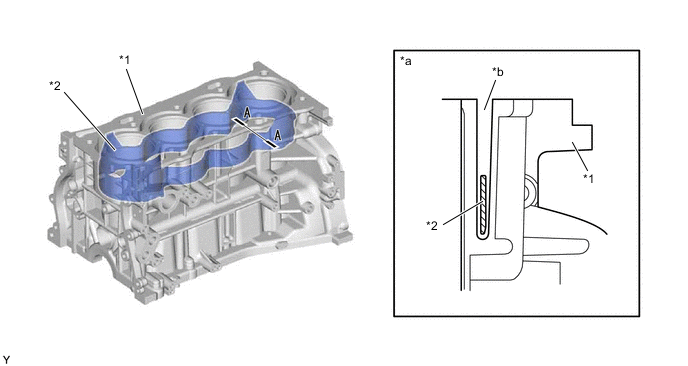
*1 Cylinder Block Sub-assembly *2 Water Jacket Spacer *a A - A Cross Section *b Water Jacket -
Blowby gas passages are provided in the crankcase.
-
Oil drain passages are provided in the crankcase. This prevents the crankshaft from mixing the engine oil, which reduces rotational resistance.
-
The oil filter bracket is integrated into the crankcase.
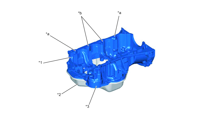
*1 Stiffening Crank Case Assembly *2 Oil Pan Sub-assembly *3 Oil Filter Bracket - - *a Oil Drain Passage *b Blowby Gas Passage
-