HYBRID CONTROL SYSTEM
-
CONSTRUCTION
-
The hybrid system uses motive force provided by the engine, MG2 and MGR*, and the system uses MG1 primarily as a generator. The system optimally combines these forces in accordance with various driving conditions.
-
The hybrid vehicle control ECU constantly monitors the State Of Charge (SOC) of the HV battery, the HV battery temperature, the engine coolant temperature and the electrical load condition. If any one of the monitoring items fails to satisfy requirements when the READY indicator light is on and the shift lever is in P, R, D or S, or if the vehicle is driven in reverse, the hybrid vehicle control ECU demands an engine start to drive MG1 in order to charge the HV battery.
-
MGR drives the rear wheels in accordance with the driving conditions of the vehicle, thus enhancing the communication of vehicle motive force to the road.*
-
The hybrid system drives the vehicle by optimally combining the operation of the engine, MG1, MG2 and MGR* in accordance with the driving conditions listed in the table below
-
*: AWD models
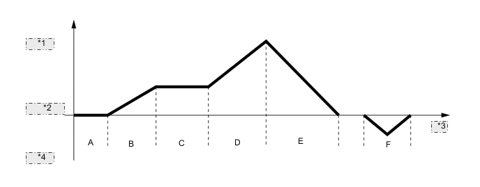
*1 Forward *2 Vehicle Speed *3 Time *4 Reverse Driving Condition A READY-ON State B Starting Off C Low Load Cruising Constant-speed Cruising D During Full Throttle Acceleration E During Deceleration F Driving in Reverse
-
-
-
OPERATION
-
Driving Condition A: READY-ON State
-
Even if the driver turns the power switch to on (READY), sometimes the engine will not start. If this happens, the engine, MG1, MG2 and MGR* remain stopped. The engine will only start if conditions such as engine coolant temperature, SOC of the HV battery, HV battery temperature and electrical load require an engine start.
-
*: AWD models
-
-
After driving, if the driver stops the vehicle and moves the shift lever to P, the hybrid vehicle control ECU will continue to operate the engine. The engine will continue to operate until SOC of the HV battery, engine coolant temperature, HV battery temperature and/or electrical load conditions reach a specified level.
-
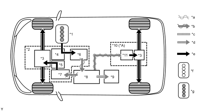
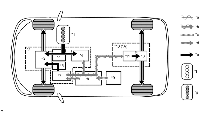
If any of the items monitored by the hybrid vehicle control ECU indicates the need for an engine start when the READY indicator light is on and the shift lever is in P, the hybrid vehicle control ECU will activate MG1 to start the engine.
-
While the engine is cranking, to prevent the reactive force of the sun gear of MG1 from rotating the ring gear and driving the drive wheels, current is also applied to MG2 in order to prevent MG2 from rotating. This function is called "reactive control"
Figure 1. READY-ON State when Starting Engine
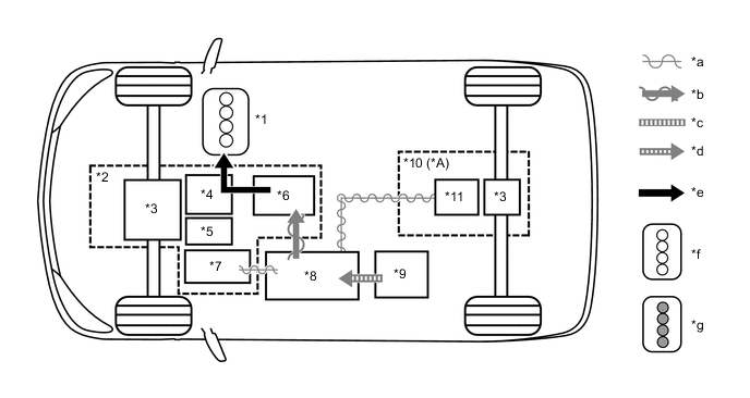
*A AWD Models - - *1 Engine *2 Hybrid Transaxle (Hybrid Vehicle Transaxle Assembly) *3 Differential *4 Power Split Planetary Gear *5 Motor Speed Reduction Planetary Gear *6 MG1 *7 MG2 *8 Inverter with Converter Assembly *9 Hybrid Battery Assembly *10 Rear Drive Unit (Rear Traction Motor with Transaxle Assembly) *11 MGR - - *a Alternating Current *b Electrical Power Path (AC) *c Direct Current (DC 244.8 V) *d Electrical Power Path (DC) *e Power Transmission Mechanical Power Path *f Engine Stopped *g Engine Running - - -
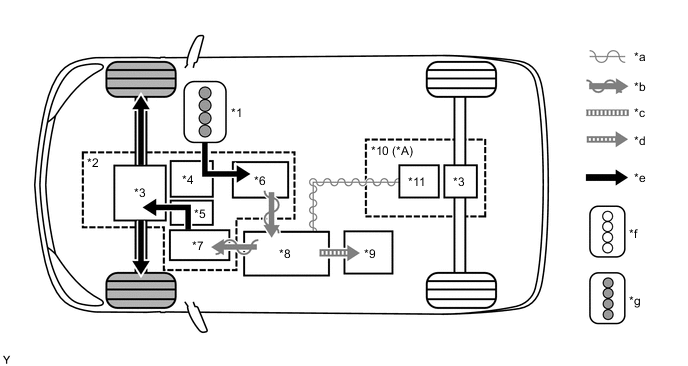
If the SOC of the HV battery is low, it is charged by MG1 which is driven by the engine.
Figure 2. Charging when Stopped
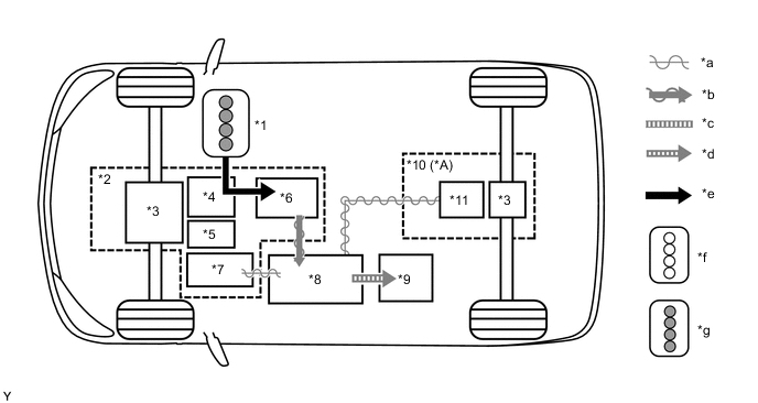
*A AWD Models - - *1 Engine *2 Hybrid Transaxle (Hybrid Vehicle Transaxle Assembly) *3 Differential *4 Power Split Planetary Gear *5 Motor Speed Reduction Planetary Gear *6 MG1 *7 MG2 *8 Inverter with Converter Assembly *9 Hybrid Battery Assembly *10 Rear Drive Unit (Rear Traction Motor with Transaxle Assembly) *11 MGR - - *a Alternating Current *b Electrical Power Path (AC) *c Direct Current (DC 244.8 V) *d Electrical Power Path (DC) *e Power Transmission Mechanical Power Path *f Engine Stopped *g Engine Running - -
-
-
Driving Condition B: Starting Off
-
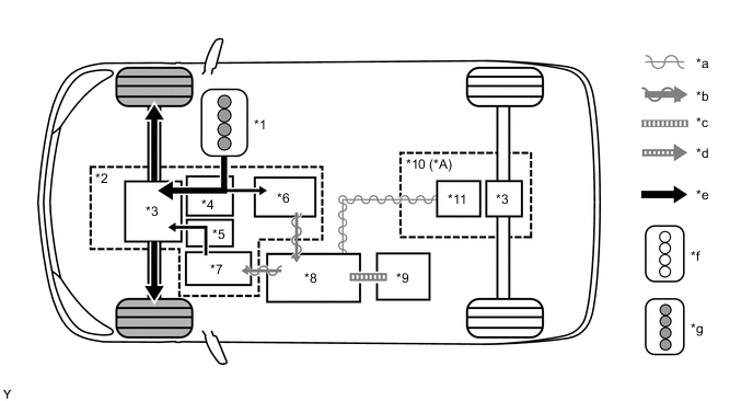
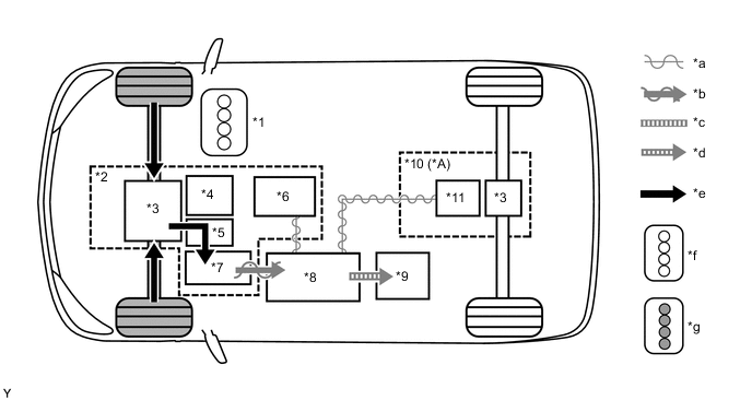
When the vehicle is started off, the vehicle operates powered by MG2 and MGR*.
-
*: AWD models
Figure 3. Starting Off
*A AWD Models - - *1 Engine *2 Hybrid Transaxle (Hybrid Vehicle Transaxle Assembly) *3 Differential *4 Power Split Planetary Gear *5 Motor Speed Reduction Planetary Gear *6 MG1 *7 MG2 *8 Inverter with Converter Assembly *9 Hybrid Battery Assembly *10 Rear Drive Unit (Rear Traction Motor with Transaxle Assembly) *11 MGR - - *a Alternating Current *b Electrical Power Path (AC) *c Direct Current (DC 244.8 V) *d Electrical Power Path (DC) *e Power Transmission Mechanical Power Path *f Engine Stopped *g Engine Running - -
-
-
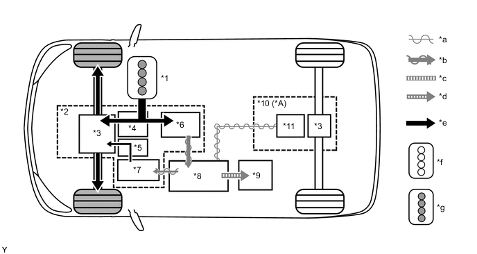
If the SOC of the HV battery is low, it is charged by MG1 which is driven by the engine. This power is also used to power MG2 and MGR*.
-
*: AWD models
Figure 4. Starting Off when SOC Low
*A AWD Models - - *1 Engine *2 Hybrid Transaxle (Hybrid Vehicle Transaxle Assembly) *3 Differential *4 Power Split Planetary Gear *5 Motor Speed Reduction Planetary Gear *6 MG1 *7 MG2 *8 Inverter with Converter Assembly *9 Hybrid Battery Assembly *10 Rear Drive Unit (Rear Traction Motor with Transaxle Assembly) *11 MGR - - *a Alternating Current *b Electrical Power Path (AC) *c Direct Current (DC 244.8 V) *d Electrical Power Path (DC) *e Power Transmission Mechanical Power Path *f Engine Stopped *g Engine Running - -
-
-
-
Driving Condition C: Low Load Cruising
-
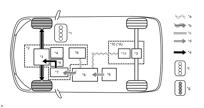
When the vehicle is running under low load cruising conditions, the vehicle operates powered by MG2.
Figure 5. Low Load Cruising

*A AWD Models - - *1 Engine *2 Hybrid Transaxle (Hybrid Vehicle Transaxle Assembly) *3 Differential *4 Power Split Planetary Gear *5 Motor Speed Reduction Planetary Gear *6 MG1 *7 MG2 *8 Inverter with Converter Assembly *9 Hybrid Battery Assembly *10 Rear Drive Unit (Rear Traction Motor with Transaxle Assembly) *11 MGR - - *a Alternating Current *b Electrical Power Path (AC) *c Direct Current (DC 244.8 V) *d Electrical Power Path (DC) *e Power Transmission Mechanical Power Path *f Engine Stopped *g Engine Running - - -
If the SOC of the HV battery is low, it is charged by MG1 which is driven by the engine. This power is also used to power MG2.
Figure 6. Low Load Cruising when SOC Low
*A AWD Models - - *1 Engine *2 Hybrid Transaxle (Hybrid Vehicle Transaxle Assembly) *3 Differential *4 Power Split Planetary Gear *5 Motor Speed Reduction Planetary Gear *6 MG1 *7 MG2 *8 Inverter with Converter Assembly *9 Hybrid Battery Assembly *10 Rear Drive Unit (Rear Traction Motor with Transaxle Assembly) *11 MGR - - *a Alternating Current *b Electrical Power Path (AC) *c Direct Current (DC 244.8 V) *d Electrical Power Path (DC) *e Power Transmission Mechanical Power Path *f Engine Stopped *g Engine Running - -
-
-
Driving Condition C: Constant-speed Cruising
-
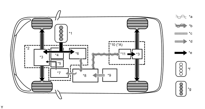
When the vehicle is running under constant-speed cruising conditions, the engine will be operated in its most efficient range to power the vehicle.
-
The motive force from the engine is split into two in the power split planetary gear unit. One portion of the motive force is used to drive the wheels directly and the other is used to generate electricity using MG1.
-
The electricity from MG1 is used to drive MG2. This supports the directly transmitted engine motive force, contributing to fuel efficiency.
-
MGR is not used to output motive force in the constant speed cruising mode, in order to make fuel economy a priority.*
-
*: AWD models
Figure 7. Constant-speed Cruising
*A AWD Models - - *1 Engine *2 Hybrid Transaxle (Hybrid Vehicle Transaxle Assembly) *3 Differential *4 Power Split Planetary Gear *5 Motor Speed Reduction Planetary Gear *6 MG1 *7 MG2 *8 Inverter with Converter Assembly *9 Hybrid Battery Assembly *10 Rear Drive Unit (Rear Traction Motor with Transaxle Assembly) *11 MGR - - *a Alternating Current *b Electrical Power Path (AC) *c Direct Current (DC 244.8 V) *d Electrical Power Path (DC) *e Power Transmission Mechanical Power Path *f Engine Stopped *g Engine Running - -
-
-
If the SOC of the HV battery is low, more engine power is provided to increase the generation of electricity via MG1. This charges the HV battery.
Figure 8. Constant-speed Cruising when SOC Low
*A AWD Models - - *1 Engine *2 Hybrid Transaxle (Hybrid Vehicle Transaxle Assembly) *3 Differential *4 Power Split Planetary Gear *5 Motor Speed Reduction Planetary Gear *6 MG1 *7 MG2 *8 Inverter with Converter Assembly *9 Hybrid Battery Assembly *10 Rear Drive Unit (Rear Traction Motor with Transaxle Assembly) *11 MGR - - *a Alternating Current *b Electrical Power Path (AC) *c Direct Current (DC 244.8 V) *d Electrical Power Path (DC) *e Power Transmission Mechanical Power Path *f Engine Stopped *g Engine Running - -
-
-
Driving Condition D: during Full Throttle Acceleration
-
When the vehicle driving condition changes from low load cruising and constant-speed cruising to full throttle acceleration, the system supplements the motive force of MG2 with electrical power from the HV battery.
-
MGR operates during full throttle acceleration and drives the rear wheels in order to make acceleration performance a priority.*
-
*: AWD models
Figure 9. During Full Throttle Acceleration
*A AWD Models - - *1 Engine *2 Hybrid Transaxle (Hybrid Vehicle Transaxle Assembly) *3 Differential *4 Power Split Planetary Gear *5 Motor Speed Reduction Planetary Gear *6 MG1 *7 MG2 *8 Inverter with Converter Assembly *9 Hybrid Battery Assembly *10 Rear Drive Unit (Rear Traction Motor with Transaxle Assembly) *11 MGR - - *a Alternating Current *b Electrical Power Path (AC) *c Direct Current (DC 244.8 V) *d Electrical Power Path (DC) *e Power Transmission Mechanical Power Path *f Engine Stopped *g Engine Running - -
-
-
-
Driving Condition E: during Deceleration
-
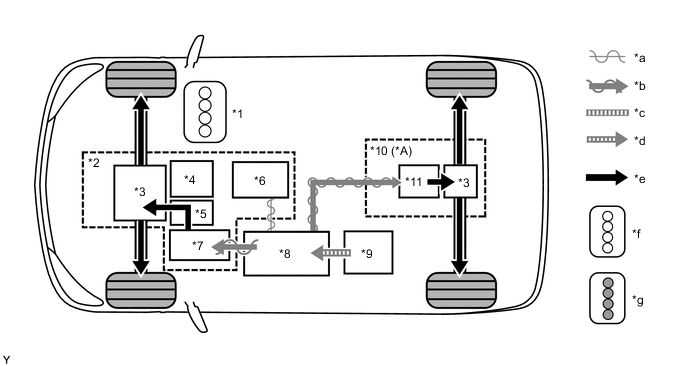
While the vehicle is being driven with the shift lever in D and it decelerates, the engine turns off and the engine motive force output to the wheels will be zero. At this time, the wheels drive MG2, causing MG2 to operate as generators and charge the HV battery. While MG2 is operating as generators, they create a resistance to rotation at the wheels, producing a braking effect.
-
If the vehicle decelerates at a higher speed, the engine (crankshaft) will not stop turning. The engine will maintain a predetermined speed in order to protect the planetary gear unit. This operation is not shown in the following diagrams.
Figure 10. During Deceleration
*A AWD Models - - *1 Engine *2 Hybrid Transaxle (Hybrid Vehicle Transaxle Assembly) *3 Differential *4 Power Split Planetary Gear *5 Motor Speed Reduction Planetary Gear *6 MG1 *7 MG2 *8 Inverter with Converter Assembly *9 Hybrid Battery Assembly *10 Rear Drive Unit (Rear Traction Motor with Transaxle Assembly) *11 MGR - - *a Alternating Current *b Electrical Power Path (AC) *c Direct Current (DC 244.8 V) *d Electrical Power Path (DC) *e Power Transmission Mechanical Power Path *f Engine Stopped *g Engine Running - -
-
-
Driving Condition F: Driving in Reverse
-
While the vehicle is being driven in reverse, its power is delivered by MG2. At this time, MG2 is spinning in the opposite (-) direction of forward travel, the engine can remain stopped, and MG1 is spinning in the (+) direction without generating electricity.
-
In addition, when more motive force is needed, power is also provided to MGR.*
-
While driving in reverse, when any of the conditions monitored by the hybrid vehicle control ECU such as SOC of the HV battery, HV battery temperature, engine coolant temperature and electrical load condition reach a specified level, MG1 will be used to start the engine. The following illustration represents an example when the engine is not running:
-
*: AWD models
Figure 11. Driving in Reverse
*A AWD Models - - *1 Engine *2 Hybrid Transaxle (Hybrid Vehicle Transaxle Assembly) *3 Differential *4 Power Split Planetary Gear *5 Motor Speed Reduction Planetary Gear *6 MG1 *7 MG2 *8 Inverter with Converter Assembly *9 Hybrid Battery Assembly *10 Rear Drive Unit (Rear Traction Motor with Transaxle Assembly) *11 MGR - - *a Alternating Current *b Electrical Power Path (AC) *c Direct Current (DC 244.8 V) *d Electrical Power Path (DC) *e Power Transmission Mechanical Power Path *f Engine Stopped *g Engine Running - -
-
-
-
Driving on Slippery Surface (AWD Models)
-
When the front tires slip while driving on a slippery surface, MGR operates while part of the electricity generated by MG1 is supplied to MGR from MG2 to stabilize the vehicle.
-
When the electricity generated by MG1 is insufficient, electricity is also supplied from the HV battery.
-
Engine output is limited as necessary.
-
The skid control ECU performs TRC or VSC control by sending requests to decrease the motive force to the hybrid vehicle control ECU.
Figure 12. Driving on Slippery Surface
*A AWD Models - - *1 Engine *2 Hybrid Transaxle (Hybrid Vehicle Transaxle Assembly) *3 Differential *4 Power Split Planetary Gear *5 Motor Speed Reduction Planetary Gear *6 MG1 *7 MG2 *8 Inverter with Converter Assembly *9 Hybrid Battery Assembly *10 Rear Drive Unit (Rear Traction Motor with Transaxle Assembly) *11 MGR - - *a Alternating Current *b Electrical Power Path (AC) *c Direct Current (DC 244.8 V) *d Electrical Power Path (DC) *e Power Transmission Mechanical Power Path *f Engine Stopped *g Engine Running - -
-
-