HYBRID CONTROL SYSTEM
-
CONSTRUCTION
-
Inverter with Converter Assembly
-
The inverter with converter assembly has a multi-layer structure which consists of the Motor Generator ECU (MG ECU), boost converter, inverter, condenser and hybrid vehicle converter assembly, achieving a lightweight and compact design.
-
An inverter current sensor, inverter temperature sensor and atmospheric pressure sensor are provided in the inverter with converter assembly in order to optimally control the boost converter and inverter.
-
The inverter with converter assembly is cooled by the dedicated radiator of a cooling system that is separate from that of the engine cooling system.
-
This inverter has a cooling system with a structure that makes it possible to cool the Insulated Gate Bipolar Transistors (IGBTs) of the boost converter and the inverter from both sides, contributing to a compact design.
-
In consideration of safety, interlock switches are provided for the inverter with converter assembly. The interlock switches turn off the System Main Relays (SMRs) when the inverter UPR covers or connector cover assembly is removed or the connector of the inverter hybrid connector assembly is disconnected.
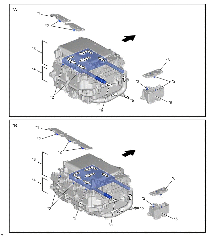
*A 2WD Models *B AWD Models *1 Inverter UPR Cover *2 Interlock Switch *3 Control Circuit Portion
-
Inverter
-
Boost Converter
-
Motor Generator ECU (MG ECU)
-
Atmospheric Pressure Sensor
*4 Condenser/Hybrid Vehicle Converter Assembly Portion *5 Inverter Hybrid Connector Assembly *6 Connector Cover Assembly *a Coolant Outlet *b Coolant Inlet 
Front 
Coolant Flow 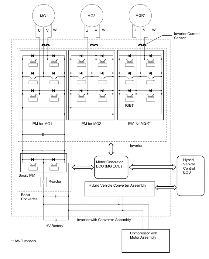
-
-
-
MG ECU
-
The Motor Generator ECU (MG ECU) is provided in the inverter with converter assembly. In accordance with signals received from the hybrid vehicle control ECU, the MG ECU controls the boost converter and inverter in order to drive MG1, MG2 or MGR* or to cause them to generate electricity.
-
The MG ECU transmits information that is required for vehicle control, such as the inverter output amperage, inverter temperature and failure information, to the hybrid vehicle control ECU. The ECU receives information that is required for controlling the motor generators, such as the required motive force or the motor temperature, from the hybrid vehicle control ECU.
-
*: AWD models
-
-
-
Inverter Current Sensor
-
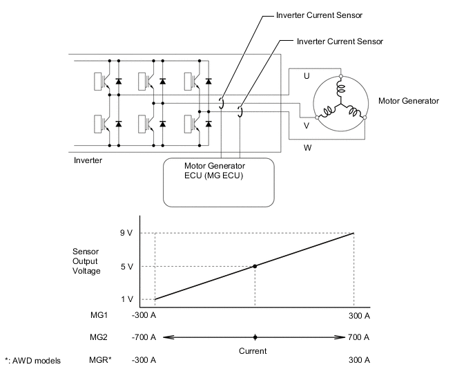
For the 3-phase AC used to drive MG1, MG2 and MGR*, there are current sensors for the V and W phases. The actual current value is measured, and used as feedback by the Motor Generator ECU (MG ECU).
-
*: AWD models
-
-
If the current value of 2 phases (V and W phases) is measured, the current of the U phase can be determined, even though it is not equipped with a current sensor (U phase current + V phase current + W phase current = 0).
-
-
Inverter Temperature Sensor
-
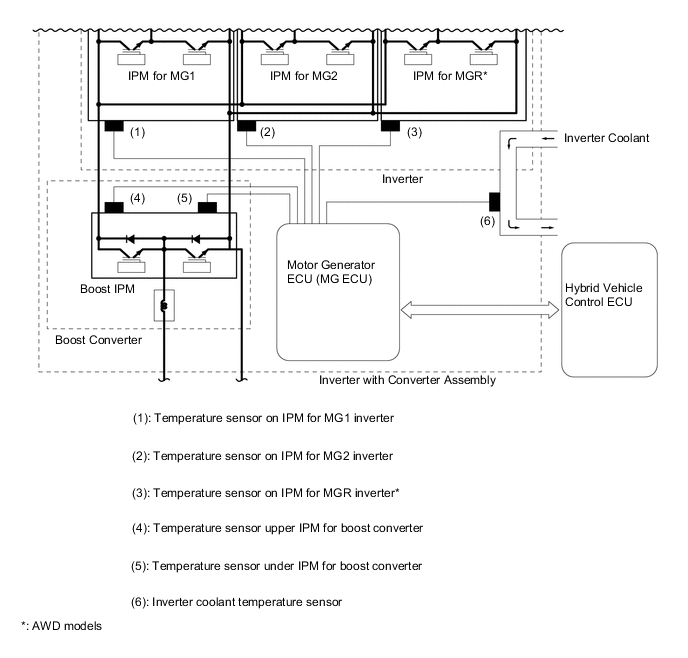
In the inverter with converter assembly for 2WD models, there are 5 different temperature sensors, including 1 sensor for the coolant temperature, 2 sensors for the boost converter and 1 sensor each for the Intelligent Power Modules (IPMs) for MG1 and MG2.
-
In the inverter with converter assembly for AWD models, there are 6 different temperature sensors, including 1 sensor for the coolant temperature, 2 sensors for the boost converter and 1 sensor each for the Intelligent Power Modules (IPMs) for MG1, MG2 and MGR.
-
The Motor Generator ECU (MG ECU) confirms the effectiveness of the hybrid cooling system based on the temperature information sent from these sensors. In addition, inverter output is limited when the temperature is high.
-
-
Atmospheric Pressure Sensor
-
An atmospheric pressure sensor is provided on the MG ECU board. The sensor detects atmospheric pressure and transmits a signal to the MG ECU to allow corrections that correspond to the usage environment.
-
-