MONITOR SYSTEM
-
FUNCTION OF MAIN COMPONENTS
Component Function Television Camera Assembly Transmits a video signal of the area behind the vehicle to the radio and display receiver assembly*1 or navigation receiver assembly*2. Radio and Display Receiver Assembly*1 Displays images of the area behind the vehicle sent from the television camera assembly using the multi-display. Navigation Receiver Assembly*2 Park/Neutral Position Switch Assembly Sends an R shift position signal to the BACK UP LP relay. BACK UP LP Relay Sends an R shift position signal to the radio and display receiver assembly*1 or navigation receiver assembly*2. *1: Models with multimedia system
*2: Models with navigation system
-
SYSTEM CONTROL
-
This system operates when both the following conditions have been met:
-
The ignition switch is ON.
-
The shift lever is in R.
-
-
-
FUNCTION
-
Area Displayed on Screen
-
Objects on the right of the vehicle appear on the right side of the display panel, and objects on the left of the vehicle appear on the left side of the display panel.
-
The television camera assembly uses a wide-angle lens. The perceived distance from images that appear on the screen differs from the actual distance.
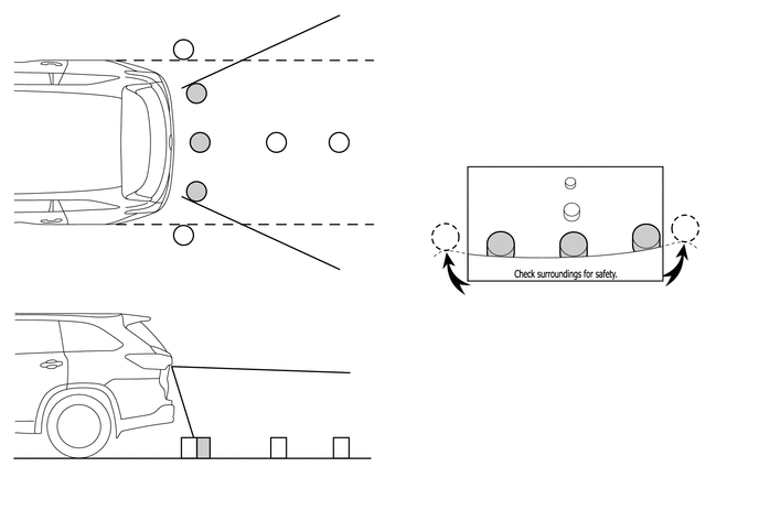
The illustration shown is an example only. The illustration may differ from the actual vehicle screen.
Note
The area displayed on the screen may vary according to vehicle status or road conditions. The area covered by the television camera assembly is limited. The television camera assembly does not show objects close to either corner of the bumper or show the area under the bumper.
-
-
Warning Message
-
A warning message appears at the bottom of the screen under the following condition. The warning message appears in the same language that has been selected by the language selector of the multi-display.
Message Appearing at Bottom of Screen Warning Message Condition Check surroundings for safety. This message always appears during system operation.
-
-
-
FAIL-SAFE
-
The table below indicates fail-safe operation when a malfunction is detected:
Malfunctioning Parts Detection Item Function Television Camera Assembly Television camera assembly malfunction signal is detected. System stops signal reception and displays a dark screen. Radio and Display Receiver Assembly*1 Malfunction of radio and display receiver assembly Stops system operation Navigation Receiver Assembly*2 Malfunction of navigation receiver assembly *1: Models with multimedia system
*2: Models with navigation system
-