BLIND SPOT MONITOR SYSTEM
-
FUNCTION OF MAIN COMPONENTS
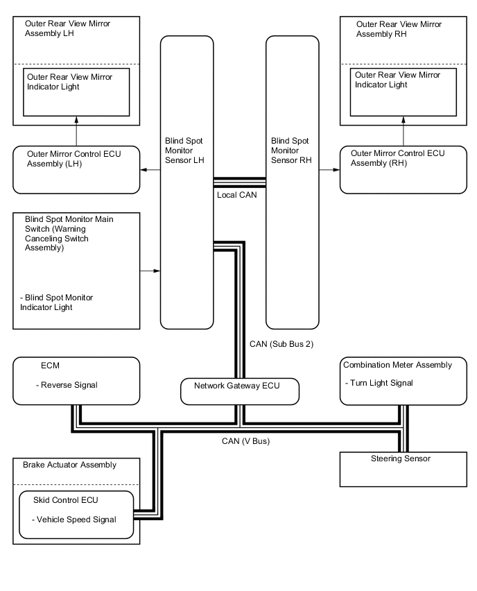
Component Function Blind Spot Monitor Sensor LH and RH
-
Outputs millimeter waves to the blind spot sensor detection area, uses the reflected millimeter waves for detecting the presence of a vehicle, the vehicle-to-vehicle distance, and the relative speed, and then transmits this information to the built-in signal processing circuit.
-
The signal processing circuit determines if a vehicle is present, and illuminates or blinks the outer rear view mirror indicator accordingly.
-
Dims the outer rear view mirror indicator light on the outer rear view mirror assembly.
Blind Spot Monitor Main Switch (Warning Canceling Switch Assembly) Turns the blind spot monitor system on or off. Blind Spot Monitor Main Switch (Warning Canceling Switch Assembly) Blind Spot Monitor ON/OFF Indicator Light When the blind spot monitor system is on, the indicator will come on. Outer Rear View Mirror Assembly LH and RH Outer Rear View Mirror Indicator Light
-
Illuminates to inform the driver that a vehicle has been detected in the blind spot detection area.
-
Flashes to inform the driver when the turn signal lever is operated if a vehicle has been detected in the blind spot detection area.
-
Flashes to inform the driver that a vehicle has been detected in the blind spot detection area while the driver is reversing.
Combination Meter Assembly Transmits the turn light signal to the blind spot monitor sensor LH and RH. Combination Meter Assembly Master Warning Light When a malfunction is detected in the blind spot monitor sensors or the blind spot monitor sensors determine that control is not possible, the master warning light illuminates and a message is displayed on the multi-information display to warn the driver. Multi-information Display Steering Sensor Transmits the steering angle signal to the blind spot monitor sensor LH and RH. Network Gateway ECU Transmits data between the CAN V bus and CAN sub bus 2. ECM Transmits the reverse signal to the blind spot monitor sensor LH and RH. Brake Actuator Assembly
-
Skid Control ECU
Transmits the vehicle speed signal to the blind spot monitor sensor LH and RH. Main Body ECU (Multiplex Network Body ECU) Transmits the destination signal, illumination signal and dimmer signal to the blind spot monitor sensor LH and RH. Outer Mirror Control ECU Assembly (LH and RH) Transmits the indicator light signal to the outer rear view mirror assembly. -
-
SYSTEM CONTROL
-
The blind spot monitor function operates when both of the following conditions are met:
-
The blind spot monitor main switch (warning canceling switch assembly) is on.
-
The vehicle speed is greater than approximately 16 km/h (10 mph).
-
-
The blind spot monitor function can detect vehicles in its detection areas.
-
The detection areas formed by the blind spot monitor sensor LH and RH are as shown below.
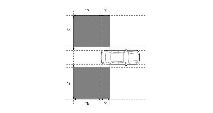
*a Approximately 3.5 m (11.5 ft) *b 3.0 m (9.8 ft) *c 1.0 m (3.3 ft) - - 
Detection Area - - -
When this vehicle is overtaken by another vehicle in the adjacent lane.
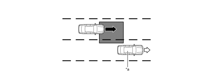
*a This Vehicle - - 
Vehicle Speed (Fast) 
Vehicle Speed (Slow) Detection Area - - -
When this vehicle overtakes another vehicle in the adjacent lane.

*a This Vehicle - - Vehicle Speed (Slow) Vehicle Speed (Fast) Detection Area - - -
When another vehicle enters the detection area of this vehicle due to a lane change.
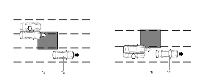
*a Other vehicle enters the detection area during lane change (merge in) (Type 1). *b Other vehicle enters the detection area during lane change (merge in) (Type 2). *c This Vehicle - - Motion direction of this vehicle Motion direction of other vehicle 
Detection Area - -
-
-
According to operation conditions, the blind spot monitor function promotes safety confirmation by using the outer rear view mirror indicator light to inform the driver that another vehicle has entered the blind spot monitor sensor detection area of this vehicle.
-
The outer rear view mirror indicator light informs the driver that a vehicle is present in the blind spot detection area by illuminating when the turn light switch is not operated, and by flashing when a vehicle is present and the turn light switch is operated.
-
-
DIAGNOSIS
-
The blind spot monitor system is equipped with a diagnosis function that can display warning messages in the multi-information display. For details, refer to the Repair Manual.
-