TOYOTA PARKING ASSIST-SENSOR SYSTEM
-
FUNCTION OF MAIN COMPONENTS
Component Function Clearance Warning ECU Assembly
-
Judges the approximate distance between the vehicle and an obstacle based on signals from the ultrasonic sensors. Output signals are sent to the combination meter assembly, radio and display receiver assembly*1, navigation receiver assembly*2, television camera assembly*4 or parking assist ECU*5.
-
Sounds the No. 1 clearance warning buzzer.
Front Corner Ultrasonic Sensor (2)*3 Detects the distance between the vehicle and an obstacle. Rear Corner Ultrasonic Sensor (2) Rear Center Ultrasonic Sensor (2) No. 1 Clearance Warning Buzzer Sounds to inform the driver according to the distance to the obstacle. Combination Meter Assembly Multi-information Display
-
Displays the location of the obstacle and the approximate distance between the vehicle and the obstacle.
-
Displays an indication of a malfunction or freezing of an ultrasonic sensor to inform the driver.
Master Warning Light Illuminates in accordance with the indication on the multi-information display. Radio and Display Receiver Assembly*1
-
Displays the location of an obstacle and the approximate distance between the vehicle and the obstacle.
-
Displays an indication of a malfunction or freezing of an ultrasonic sensor to inform the driver.
-
The sound volume, distance required to sound the buzzer and distance required to trigger the display can be chosen on the setup screen for the TOYOTA parking assist-sensor system.
-
Transmits the setup signal for the TOYOTA parking assist-sensor system to the clearance warning ECU assembly.
Navigation Receiver Assembly*2 Back Sonar or Clearance Sonar Switch Assembly Operating this switch allows the operation of the TOYOTA parking assist-sensor system to be enabled or disabled. Main Body ECU (Multiplex Network Body ECU) Sends model destination signal (information to indicate the market the vehicle was built for) to the clearance warning ECU assembly. Park/Neutral Position Switch Assembly Transmits the shift position signal to the ECM. ECM Transmits the shift position signal to the clearance warning ECU assembly. Television Camera Assembly*4
-
Captures images of the area behind the vehicle.
-
The clearance sonar information is superimposed on the captured image. Then, the image is sent to the radio and display receiver assembly*1 or navigation receiver assembly*2 as video signals.
Parking Assist ECU*5 The clearance sonar information is superimposed on the captured image. Then, the image is sent to the radio and display receiver assembly*1 or navigation receiver assembly*2 as video signals. *1: Models with multimedia system
*2: Models with navigation system
*3: Models with TOYOTA parking assist-sensor system (6-sensor type)
*4: Models with parking assist monitor system
*5: Models with panoramic view monitor system
-
-
SYSTEM CONTROL
-
Detection Area
-
The detection areas of the ultrasonic sensor are as shown in the following illustration.
-
These detection areas are applicable when positioning a 60 mm (2.36 in.) diameter pole parallel or perpendicular to the ground. The ranges vary depending on the measuring method and type of obstacle.
Figure 1. Corner Area (4-sensor Type)
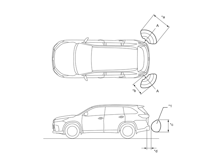
*a Approximately 1000 mm (39.4 in.) *b Approximately 600 mm (23.6 in.) *c Approximately 450 mm (17.7 in.) *d Approximately 200 mm (7.87 in.) Figure 2. Corner Area (6-sensor Type)
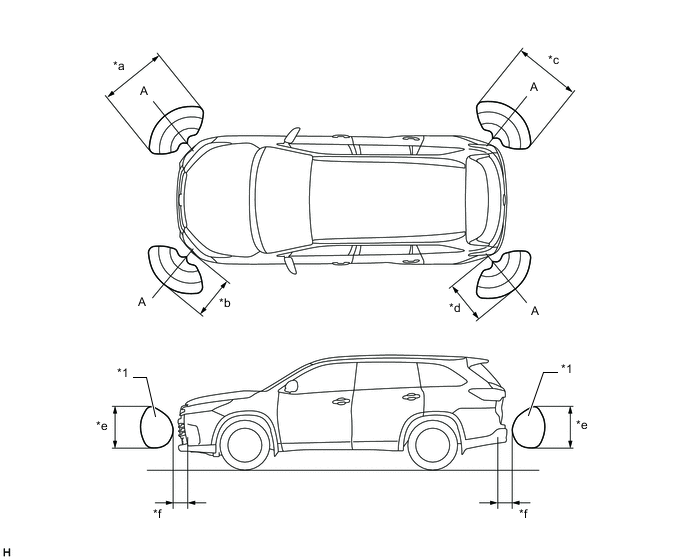
*a Approximately 1000 mm (39.4 in.) *b Approximately 600 mm (23.6 in.) *c Approximately 1000 mm (39.4 in.) *d Approximately 600 mm (23.6 in.) *e Approximately 450 mm (17.7 in.) *f Approximately 200 mm (7.87 in.) Note
The ultrasonic sensor side view detection range area (labeled*1) represents the cross section of the top view of the lines of detection range A. The area *1 does not represent the entire side view detection range.
Figure 3. Center Area
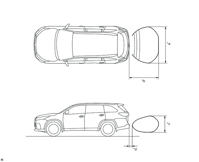
*a Approximately 1800 mm (70.9 in.) *b Approximately 1500 mm (59.1 in.) *c Approximately 500 mm (19.7 in.) *d Approximately 200 mm (7.87 in.)
-
-
The operating condition of each sensor differs according to its installed position as shown in the table below:
Installation Position Operating Condition 4-sensor Type 6-sensor Type Front Corner
-
Ignition switch is ON.
-
System is activated.
-
Shift lever is in a position other than P and R.
-
Vehicle speed is approximately 10 km/h (6 mph) or less.
- ○ Rear Corner
-
Ignition switch is ON.
-
System is activated.
-
Shift lever is in R.
○ ○ Rear Center
-
Ignition switch is ON.
-
System is activated.
-
Shift lever is in R.
○ ○ -
-
-
DIAGNOSIS
-
If a system malfunction is detected, the clearance warning ECU assembly stores Diagnostic Trouble Codes (DTCs) in its memory. For details, refer to the Repair Manual.
-