NAVIGATION SYSTEM / MULTI INFORMATION SYSTEM
-
FUNCTION OF MAIN COMPONENTS
Models with Touch System (with Navigation ECU) Component Function Radio and Display Receiver Assembly
-
Supplies power to the navigation ECU.
-
Displays a map screen or an operation screen based on image signals from the navigation ECU.
-
Sends operation signals input by touch to the navigation ECU.
Navigation ECU Controls the navigation system based on signals from the radio and display receiver assembly. Major Components of Navigation ECU Navigation Computer
-
Corrects the vehicle position based on location information calculated from the GPS, vehicle speed signals, information from built-in sensors and shift status.
-
Applies the mark of the calculated vehicle position to the map data and sends the data to the radio and display receiver assembly.
-
Sends navigation information, such as directions and route guidance, to the combination meter assembly.
Gyro Sensor Detects the vehicle's vertical axis rotation speed (yaw rate and rotation movement) and sends it to the navigation computer. GPS Receiver Demodulates GPS information received by the navigation antenna assembly, calculates the vehicle position and sends the position signal to the navigation computer. Navigation Antenna Assembly Receives GPS signals from satellites in orbit around the Earth, at an altitude of approximately 20000 km, and sends them to the radio and display receiver assembly. Parking Brake Switch Assembly Sends the parking brake position signal to the radio and display receiver assembly. Park/Neutral Position Switch Assembly Sends an R shift position signal to the BACK UP LP relay. Engine Room Relay Block and Junction Block Assembly
-
BACK UP LP Relay
Sends the R shift position signal to the radio and display receiver assembly. Window Glass Antenna Wire
-
AM
-
FM-sub
Receives radio broadcasting signals (AM/FM-sub). Window Glass Antenna Wire
-
FM
Receives radio broadcasting signals (FM). No. 1 Amplifier Antenna Assembly Amplifies radio broadcasting signals from the radio antenna and sends them to the radio and display receiver assembly. Steering Pad Switch Assembly Sends operation signals from switches such as the volume switch, mode switch and voice switch, to the spiral cable with sensor sub-assembly. Spiral Cable with Sensor Sub-assembly Sends operation signals from the steering pad switch assembly to the radio and display receiver assembly. Map Light Assembly Houses the telephone microphone assembly. Telephone Microphone Assembly Recognizes speech during voice recognition system operation and sends the audio signal to the radio and display receiver assembly. No. 1 Stereo Jack Adapter Assembly
-
Sends audio or image signals to the radio and display receiver assembly when an auxiliary device is connected.
-
Communicates with the navigation ECU via a USB communication line when a USB memory stick, portable audio player (USB type) or Apple product is connected.
Combination Meter Assembly
-
Sends vehicle speed signals to the radio and receiver assembly.
-
Displays navigation information, such as directions and route guidance, sent from the navigation receiver assembly on the multi-information display.
Models with Navigation System Component Function Navigation Receiver Assembly Receives and processes data from the built-in components, such as the electrostatic capacitive display panel which allows flick or drag operation, navigation computer, G-sensor, gyro sensor or GPS receiver and various components positioned in different parts of the vehicle, controlling the navigation system and providing various information and the operation status via the multi-display using images, voice and sounds. Major Components of Navigation Receiver Assembly Multi-display Panel
-
Displays a map screen or an operation screen based on image signals from the navigation computer.
-
Sends operation signals input by touch to the navigation computer.
Navigation Computer
-
Corrects the vehicle position based on location information calculated from the GPS, vehicle speed signals, information from built-in sensors and shift status.
-
Applies the mark of the calculated vehicle position to the map data in the microSD card (disc player disc) and sends the data to the multi-display.
-
Sends voice guidance audio signals to the speakers.
-
Sends navigation information, such as directions and route guidance, to the combination meter assembly.
Gyro Sensor Detects the vehicle's vertical axis rotation speed (yaw rate and rotation movement) and sends it to the navigation computer. GPS Receiver Demodulates GPS information received by the navigation antenna assembly, calculates the vehicle position and sends the position signal to the navigation computer. microSD Card Slot Interfaces with the microSD card (disc player disc), which contains map data, the navigation system control program, etc. microSD Card (Disc Player Disc) Contains map data and the navigation system control program, etc. Navigation Antenna Assembly Receives GPS signals from satellites in orbit around the Earth, at an altitude of approximately 20000 km, and sends them to the navigation receiver assembly. Parking Brake Switch Assembly Sends the parking brake position signal to the navigation receiver assembly. Park/Neutral Position Switch Assembly Sends an R shift position signal to the BACK UP LP relay. Engine Room Relay Block and Junction Block Assembly
-
BACK UP LP Relay
Sends the R shift position signal to the navigation receiver assembly. Window Glass Antenna Wire
-
AM
-
FM-sub
Receives radio broadcasting signals (AM/FM-sub). Window Glass Antenna Wire
-
FM
Receives radio broadcasting signals (FM). Window Glass Antenna Wire
-
DAB
Receives radio broadcasting signals (DAB). No. 1 Amplifier Antenna Assembly Amplifies radio broadcasting signals from the radio antenna and sends them to the navigation receiver assembly. Digital Audio Broadcasting Antenna Assembly Amplifies radio broadcasting signals from the radio antenna and sends them to the navigation receiver assembly. Steering Pad Switch Assembly Sends operation signals from switches such as the volume switch, mode switch and voice switch, to the spiral cable with sensor sub-assembly. Spiral Cable with Sensor Sub-assembly Sends operation signals from the steering pad switch assembly to the navigation receiver assembly. Map Light Assembly Houses the telephone microphone assembly. Telephone Microphone Assembly Recognizes speech during voice recognition system operation and sends the audio signal to the navigation receiver assembly. No. 1 Stereo Jack Adapter Assembly
-
Sends audio or image signals to the navigation receiver assembly when an auxiliary device is connected.
-
Communicates with the navigation receiver assembly via a USB communication line when a USB memory stick, portable audio player (USB type) or Apple product is connected.
Combination Meter Assembly
-
Sends vehicle speed signals to the radio and receiver assembly.
-
Displays navigation information, such as directions and route guidance, sent from the navigation receiver assembly on the multi-information display.
-
-
FUNCTION
-
Navigation Screen
-
The navigation computer calculates the present position and direction of travel, then determines a route and calculates the driving distance based on the following information sources:
- Map data in the navigation ECU*1 or microSD card (disc player disc)*2
- Global Positioning System (GPS) satellites
- Built-in gyro sensor
- Vehicle speed signal
- Reverse signal
- Parking brake signal
- Radio Data System Traffic Message Channel (RDS-TMC) signal
*1: Models with touch system (with navigation ECU)
*2: Models with navigation system
Models with Touch System (with Navigation ECU) Item Function Map Display Map Color Change Depending on the position of the light control switch, the screen changes to day mode or night mode. Taillight-interlocked Map Color Change Changes the color of the map screen that is displayed when the taillights are turned on. North Up / Heading Up
-
If North Up is selected, regardless of the direction of vehicle travel, north is always up.
-
If Heading Up is selected, the direction of vehicle travel is always up.
3D Display Displays a 3-dimensional (3D) view of the map. Multi-step Scale Display Changes the map scale in 14 steps. Street Name Indication on Scrolled Map Displays the street name and city name even when the map screen is being scrolled. Road Number Sign Board Display Displays the road number on the map. Point of Interest Display Displays selected types of points of interest as marks on the map. Route Guidance Demonstration Demonstrates the route guidance to the destination. Speed Limit Display Displays the speed limit of the road currently being travelled on. Safety Camera Display Displays safety camera icons on the map. RDS-TMC Display Displays RDS-TMC icons, arrows and indicators when RDS-TMC service is being received. Destination Search Preset Destination Memory Search Sets a pre-registered point as a destination point while driving. Address Search A destination can be set by entering a country, and town name/code name, and street/intersection name. Point of Interest Search A destination can be set in 2 ways:
-
The name of a POI can be entered and then searched for after selecting a search area. Search areas include defined areas (such as a user selected country, state and city), near the current position, near the main destination, or along the current route).
-
A POI category can be selected and searched for near the current position, in a defined area (such as a user selected country, state and city), near the main destination, or along the current route.
Online Search Allows use of an internet search engine to set a destination using the most up to date information. Previous Destination Search Stores the coordinates, names, and date of up to 100 locations that have been set as destinations in the past. Map Search A destination can be set by scrolling the cursor on the map. Coordinate Search A destination can be input by entering its coordinates. Route Search Multiple Destination Setting Sets multiple destinations. It can also rearrange the sequence of the destinations. Multiple Route Search Searches for multiple routes. Search Condition Designation Searches for the fast, short, and ecological routes. Detour Search Changes the route to detour around a section of the route. Regulated Road Consideration Performs searches which consider regulated roads. Avoid Traffic Search Manually changes to another route to avoid heavy congestion. Guidance Voice Guidance Provides voice guidance about the distance and the direction of travel to a destination point based on road conditions and vehicle speed. Next Turn Guidance Provides guidance about the distance to the next turn and indicates the direction of the turn using an arrow. Motorway (Freeway, Highway) Exit or Junction Display When the vehicle approaches an exit or junction, the motorway guidance screen will be displayed. Lane Recommendation Display When the vehicle approaches a maneuver point, the lane recommendation will be displayed. Turn List Display Displays a turn list on the right side of the 2-screen display. Distance-to-destination Display Displays the distance from the present location to the destination. Estimated Arrival Time Display Displays estimated arrival time. Models with Navigation System Item Function Map Display Taillight-interlocked Map Color Change Changes the color of the map screen that is displayed when the taillights are turned on. North Up/Heading Up
-
If North Up is selected, regardless of the direction of vehicle travel, north is always up.
-
If Heading Up is selected, the direction of vehicle travel is always up.
3D Display Displays a 3-dimensional (3D) view of the map. Multi-step Scale Display Changes the map scale in 14 steps. Footprint Map Displays a major city in a scale of 50 m (150 ft.). Point of Interest Display Displays selected types of points of interest as marks on the map. Multiple Display Function Displays different mode screens on a screen that is split into 3 views or 2 views. Current Position Display Function Displays the latitude, longitude and altitude of the current position based on the GPS signals being received. Route Guidance Demonstration Demonstrates the route guidance to the destination. Route Trace By saving a traveled route automatically or saving it manually upon reaching the destination, the routes can be displayed and retraced. RDS-TMC Display Displays RDS-TMC icons, arrows, popup messages and indicators when RDS-TMC service is being received. Destination Search Preset Destination Memory Search Sets a pre-registered point as a destination point while driving. Address Search A destination can be set by entering a country or state name, town/suburb name, street and house number. Point of Interest Search A destination can be set in 4 ways:
-
Quick search
-
Preset search
-
Category search
-
Name search
Previous Destination Search A destination can be set using the destination list in which previously set destinations are stored. Map Search A destination can be set by using the cursor on the map. Route Search Multiple Route Search Searches for multiple routes. Search Condition Designation
-
Searches for the quick, short, and alternate routes.
-
Sets whether the following routes should be avoided during route search:
-
Highways
-
Toll Roads
-
Ferries
-
Unsealed Roads
-
4WD Tracks
Adds Waypoints Adds waypoints along with the set route to set the pass points. Traffic Congestion Information Consideration Performs searches which consider traffic congestion information. Auto Avoid Traffic Search Automatically changes to another route to avoid heavy congestion. Auto Re-route Search Performs automatic re-route search if the vehicle deviates from the set route. Guidance Voice Guidance Provides voice guidance about the distance and the direction of travel to a destination point based on road conditions and vehicle speed. Next Turn Guidance Provides guidance about the distance to the next turn and indicates the direction of the turn using an arrow. Lane Information Guidance Provides lane information and indicates the lane to be driven in when the vehicle is on a multiple lane road. Signposts Display Displays lane information similar to overhead road traffic signs on the top of the map screen. Real Highway/Motorway Junction Display Displays the junction and signage in 3D in the vicinity of a major junction while driving. Route Status Information Display Displays route data items that the driver selects to display, such as the current vehicle speed or altitude, in the data fields at the corner of the map screen. Route data related to the destination or following way points also can be displayed. Route Progress Bar Display Displays the progress made on the current route using the route progress bar to the left of the map screen. Others Voice Recognition Recognizes pre-programmed system commands spoken to operate the navigation system. -
-
-
Setup Screen
-
The settings for the functions of the multi-display are available from the setup screen.
Models with Touch System (with Navigation ECU) Item Function General Setting
-
The language can be selected.
-
The voice guidance volume can be adjusted or switched off.
-
Phone voice volume can be adjusted.
-
Ring volume can be adjusted.
-
The unit of measurement for fuel consumption can be changed.
-
The beep sound can be turned off.
-
Automatic text scrolling can be turned off.
-
Data can be stored on a USB memory device.
-
Data can be copied from a USB memory device.
-
Registered information (personal data) can be cleared.
-
System information
-
Third party software information used in the navigation system, such as notices, can be displayed.
Display Settings
-
Day mode can be set (the screen remains in day mode regardless of the position of the headlight switch).
-
The screen can be turned off.
-
Map Menu, Camera and Video screen adjustment
Audio Settings Sound quality can be adjusted. Connectivity Settings
-
The connection to a Bluetooth device can be turned on or off.
-
Connectable Bluetooth devices can be searched for.
-
The names of the Bluetooth devices that are currently connected or that are in the connection history can be displayed in a list. Additionally, availability information for each Bluetooth device is displayed.
-
PIN codes used for Bluetooth connection certification can be set.
-
A profile for connecting to the internet can be set.
-
A Toyota web account can be set.
Phone Settings
-
Message reception notification can be turned on or off.
-
E-mail reception notification can be turned on or off.
-
The ring tone can be changed or turned off.
-
Phone book data stored on a cellular phone can be transferred manually.
Vehicle Settings
-
Customizable vehicle settings can be changed.
-
Back camera guide line settings can be changed.
Models with Navigation System Item Function General Settings
-
Time zones and the on/off setting of daylight saving time can be changed.
-
The unit of measurement for fuel consumption can be changed.
-
The beep sound can be turned off.
-
The color of the screen buttons can be changed.
-
Keyboard layout can be changed.
-
Automatic return from the audio screen to the home screen after audio operation can be changed.
-
The capacitive touch button sensor sensitivity can be changed.
-
Animations can be set to on/off.
-
The opening image can be changed.
-
The screen off image can be changed.
-
Registered information (personal data) can be cleared.
-
Navigation system program can be updated.
-
Third party software information used in the navigation system, such as notices, can be displayed.
Home Screen Settings The display items/area on the home screen can be changed. Voice Settings
-
The voice guidance volume can be adjusted or switched off.
-
Voice guidance during route guidance can be set.
-
Voice recognition prompts can be set.
-
Voice recognition prompt interruption can be set to on/off.
Display Settings Map Menu, Camera and Video screen can be adjusted. Bluetooth Settings
-
Bluetooth devices can be registered.
-
Bluetooth devices can be deleted.
-
Bluetooth devices can be selected.
-
Bluetooth devices can be edited.
-
Bluetooth system settings can be changed:
-
Automatic connection to a Bluetooth device
-
Bluetooth device name
-
Bluetooth device PIN-code
-
Bluetooth device address
-
Display of Bluetooth device connection status
-
Bluetooth device profile
Telephone/Message Settings
-
A Bluetooth phone can be registered or connected.
-
Telephone sound settings can be changed:
-
Ring Tone
-
Ring Tone Volume
-
Message Readout volume
-
SMS/MMS Incoming Tone
-
SMS/MMS Incoming Tone Volume
-
E-mail Incoming Tone
-
E-mail Incoming Tone Volume
-
In-call Volume
-
Contact/Call history settings can be changed:
-
Automatic contact/history transfer function settings when a PBAP compatible Bluetooth phone is connected
-
Contacts update
-
Contacts sorting
-
Favorites list registration
-
Contacts deletion from the favorites list
-
Contact image display
-
Call history deletion*
-
New contact addition to the contact list*
-
Contact list editing*
-
Contact deletion from the contact list*
-
Message function settings can be changed:
-
Message forwarding from cellular phones
-
Automatic message readout
-
SMS/MMS notification popup
-
E-mail notification popup
-
Vehicle signature on outgoing messages
-
Message read status on phone update
-
Incoming SMS/MMS display when an SMS/MMS message is received
"Full Screen": The incoming SMS/MMS display screen is displayed and can be operated on the screen.
"Drop-Down": A message is displayed on the upper side of the screen and can be operated only via the steering wheel switches.
-
Incoming E-mail display when an E-mail is received
"Full Screen": The incoming E-mail display screen is displayed and can be operated on the screen.
"Drop-Down": A message is displayed on the upper side of the screen and can be operated only via the steering wheel switches.
-
Display of messaging account names on the inbox tab
-
Telephone display settings can be changed:
-
Incoming call display
-
Display of the automatic contact/history transfer completion message
Audio Settings
-
FM radio settings can be changed:
-
Refreshing of station list
-
Radio text display on/off settings
-
DAB radio settings
-
iPod settings
-
External video settings
-
Cover art settings can be changed.
Toyota Link
-
The voice guidance volume can be adjusted or switched off.
-
The pop up reminder for cellular phone data usage can be set.
Vehicle
-
Customizable vehicle settings can be changed.
-
TOYOTA park assist settings can be changed.
-
Back camera guide line settings can be changed.
Screen Off The screen can be turned off. *: For PBAP compatible models
-
-
-
Fuel Consumption Screen
-
The fuel consumption screen is displayed as illustrated below. This screen has the display functions listed below.
Figure 1. Models with Touch System (with Navigation ECU)
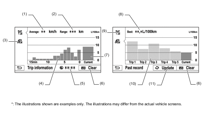
Item Outline (1) Average Speed Displays an average speed value that has been calculated by the combination meter assembly, which is based on the distance driven and time elapsed since the ignition switch is turned to ON. (2) Cruising Range Displays the approximate drivable distance. (3) Past Record Switch Changes to the past record (per trip) fuel consumption screen. (4) Average Per Minute Fuel Consumption
-
Displays the value that has been calculated by the combination meter assembly, which is based on the driven distance and the volume of fuel consumed (fuel injection signal) since the ignition switch was turned to ON.
-
Displays the average fuel consumption for the last minute, or since clear was last selected.
(5) Elapsed Time Displays the value that has been calculated by the combination meter assembly, which is based on the time elapsed since the ignition switch is turned to ON. (6) Clear Switch Clears all past information. (7) Current Per Minute Fuel Consumption Displays the instantaneous (current) fuel consumption value that has been calculated by the combination meter assembly, which is based on the driven distance and the volume of fuel consumed (fuel injection signal) since the ignition switch was turned to ON. (8) Best Fuel Consumption Displays the best (most economical) per trip fuel consumption. (9) Trip Information Switch Changes to the average per minute fuel consumption screen. (10) Average Per Trip Fuel Consumption
-
Displays the current record and the last 5 average per trip fuel consumption records or the current record and those since clear was last selected.
-
Starts calculating the average fuel consumption when the average fuel consumption displayed on the combination meter assembly is reset.
(11) Update Switch
-
Restarts calculation of the average fuel consumption value.
-
Sends the average fuel consumption reset signal to the combination meter assembly to update the graph.
Figure 2. Models with Navigation System
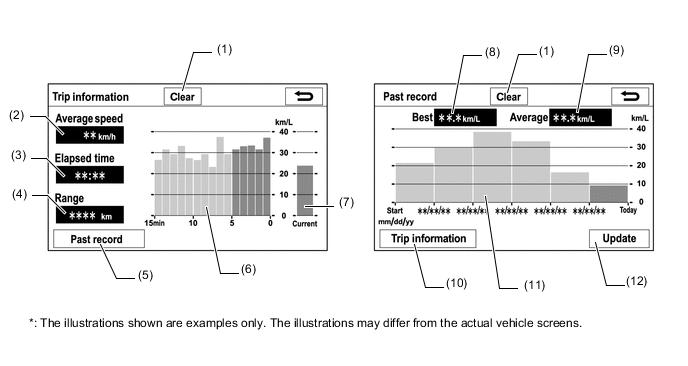
Item Outline (1) Clear Switch Clears all past information. (2) Average Speed Displays an average speed value that has been calculated by the combination meter assembly, which is based on the distance driven and time elapsed since the ignition switch was turned to ON. (3) Elapsed Time Displays an elapsed time value that has been calculated by the combination meter assembly, which is based on the time elapsed since the ignition switch was turned to ON. (4) Range Displays the approximate drivable distance. (5) Past Record Switch Changes to the Past record (per trip) fuel consumption screen. (6) Average Per Minute Fuel Consumption
-
Displays the value that has been calculated by the combination meter assembly, which is based on the driven distance and the volume of fuel consumed (fuel injection signal) since the ignition switch was turned to ON.
-
Displays the average fuel consumption for the last minute, or since clear was last selected.
(7) Current Per Minute Fuel Consumption Displays the instantaneous (current) fuel consumption value that has been calculated by the combination meter assembly, which is based on the driven distance and the volume of fuel consumed (fuel injection signal) since the ignition switch was turned to ON. (8) Best Fuel Consumption Displays the best (most economical) per trip fuel consumption. (9) Average Fuel Consumption Displays the average fuel consumption for this trip and the previous 5 trips. (10) Trip Information Switch Changes to the average per minute fuel consumption screen. (11) Average Per Trip Fuel Consumption
-
Displays the current record and the last 5 average per trip fuel consumption records or the current record and those since clear was last selected.
-
Starts calculating the average fuel consumption when the average fuel consumption displayed on the combination meter assembly is reset.
(12) Update Switch
-
Restarts calculation of the average fuel consumption value.
-
Sends the average fuel consumption reset signal to the combination meter assembly to update the graph.
-
-
-
-
DIAGNOSIS
-
For details on the procedure required to enter the Service Menu screen, refer to the Repair Manual.
-