PARKING ASSIST MONITOR SYSTEM
-
FUNCTION OF MAIN COMPONENTS
Component Function Television Camera Assembly
-
Captures images of the area behind the vehicle.
-
The parking assist guide lines that are calculated based on signals from the steering sensor are superimposed on the captured image. Then, the image is sent to the navigation receiver assembly as video signals.
-
When the back door is open, superimposing of parking assist guide lines is canceled and only the captured image is sent as video signals.
Radio and Display Receiver Assembly*1 Displays images of the area behind the vehicle sent from the television camera assembly using the multi-display. Navigation Receiver Assembly*2 Steering Sensor Detects the angle of the steering wheel and sends the resulting signals to the television camera assembly. Park/Neutral Position Switch Assembly Sends an R shift position signal to the BACK UP LP relay. Engine Room Relay Block and Junction Block Assembly
-
BACK UP LP Relay
Sends an R shift position signal to the navigation receiver assembly. Power Steering ECU Assembly Sends the steering type information signal to the television camera assembly. Back Door Lock Assembly
-
Back Door Courtesy Switch
Sends the back door courtesy switch signal to the multiplex network door ECU. Multiplex Network Door ECU Sends the back door courtesy switch signal to the main body ECU (multiplex network body ECU). Main Body ECU (Multiplex Network Body ECU) Sends the back door courtesy switch signal to the television camera assembly. Network Gateway ECU Relays and transmits data between CAN buses. *1: Models with touch system
*2: Models with navigation system
-
-
SYSTEM CONTROL
-
The parking assist monitor system operates when both of the following conditions are met:
-
The ignition switch is ON.
-
The shift lever is in R.
-
-
-
FUNCTION
-
Area Displayed on Screen
-
Objects on the right of the vehicle appear on the right side of the multi-display, and objects on the left of the vehicle appear on the left side of the multi-display.
-
The television camera assembly uses a wide-angle lens. The perceived distance from images that appear on the screen differs from the actual distance.
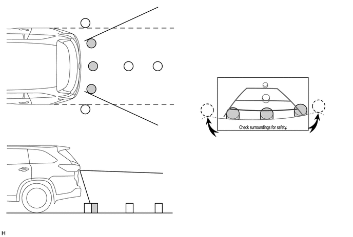
Note
The area displayed on the screen may vary according to vehicle status or road conditions. The area covered by the television camera assembly is limited. The television camera assembly does not show objects close to either corner of the bumper or show the area under the bumper.
-
-
Warning Message
-
A warning message appears at the bottom of the screen under the following conditions. The warning message appears in the same language that has been selected by the language selector of the multi-display.
Messages Appearing at Bottom of Screen Warning Message Condition Check surroundings for safety. This message always appears during system operation.
-
-
-
FAIL-SAFE
-
The table below indicates the malfunction detection items for the components in this system.
Malfunctioning Parts Detection Item Function Television Camera Assembly Camera malfunction signal is detected Stops system operation and displays a dark screen Steering Sensor
-
Sensor malfunction is detected
-
Sensor open circuit signal is detected
-
Communication malfunction between the steering sensor and television camera assembly
Stops system operation Neutral steering point correction incomplete signal is detected Radio and Display Receiver Assembly*1 Malfunction of radio and display receiver assembly Navigation Receiver Assembly*2 Malfunction of navigation receiver assembly *1: Models with touch system
*2: Models with navigation system
-
-
-
DIAGNOSIS
-
The radio and display receiver assembly*1 or navigation receiver assembly*2 is equipped with a diagnosis function which can display a diagnosis menu for the parking assist monitor system. The method for entering the diagnosis menu screen is the same as the method used for the multi-display. For details, refer to the Repair Manual.
*1: Models with touch system
*2: Models with navigation system
-