BRAKE CONTROL SYSTEM
-
OPERATION
-
ABS and EBD
-
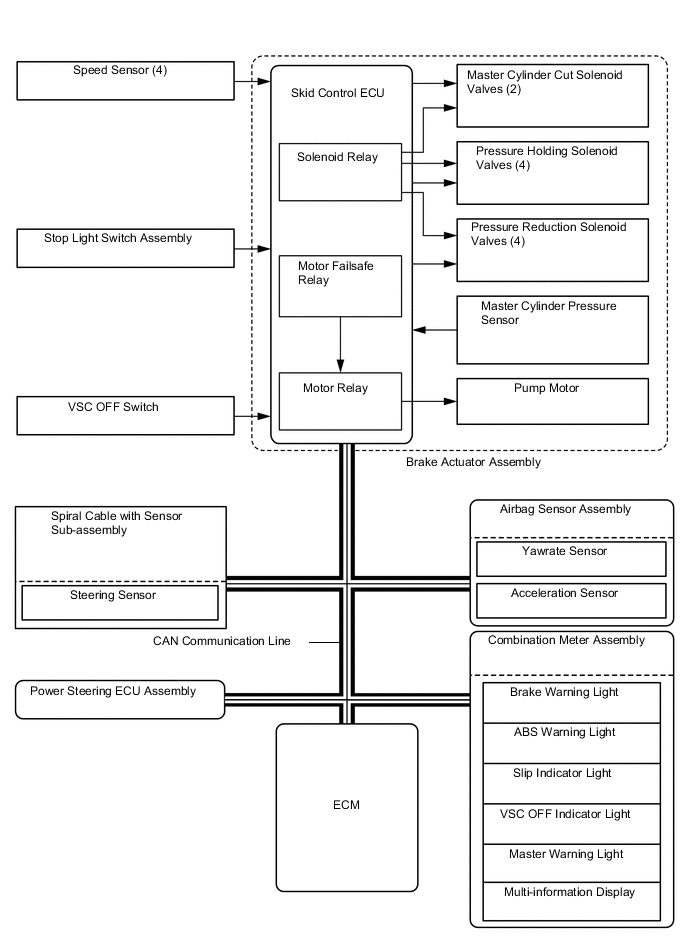
Based on the signals received from the 4 speed sensors, the skid control ECU calculates the speed of each wheel, and checks the wheel slipping conditions. In accordance with the slipping condition, the skid control ECU controls each solenoid valve in the brake actuator assembly in order to adjust the fluid pressure of each wheel cylinder in the following 3 modes: pressure increase, pressure holding, and pressure reduction modes.
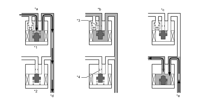
*1 Pressure Holding Solenoid Valve *2 Pressure Reduction Solenoid Valve *3 Port A *4 Port B *a Pressure Increase Mode *b Pressure Holding Mode *c Pressure Reduction Mode *d To Wheel Cylinder *e From Wheel Cylinder - - Pressure Mode Increase Mode Holding Mode Reduction Mode Pressure Holding Solenoid Valve (Port A) Off (Open) On (Closed) On (Closed) Pressure Reduction Solenoid Valve (Port B) Off (Closed) Off (Closed) On (Open) Wheel Cylinder Pressure Increases Holds Reduces
-
-
Brake Assist
-
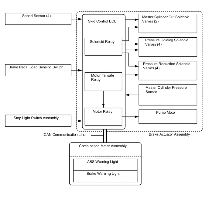
In the event of emergency braking, the skid control ECU determines the driver's intentions based on the speed of the pressure increase in the master cylinder detected by the master cylinder pressure sensor signal. If the skid control ECU judges the need for additional brake assist, pressure to supplement the amount provided by the master cylinder is generated by the pump in the brake actuator and directed to each wheel cylinder.
-
The skid control ECU also provides brake assist in the event of a brake booster failure. The skid control ECU judges a brake booster failure using the brake load sensing switch and master cylinder pressure sensor signals.
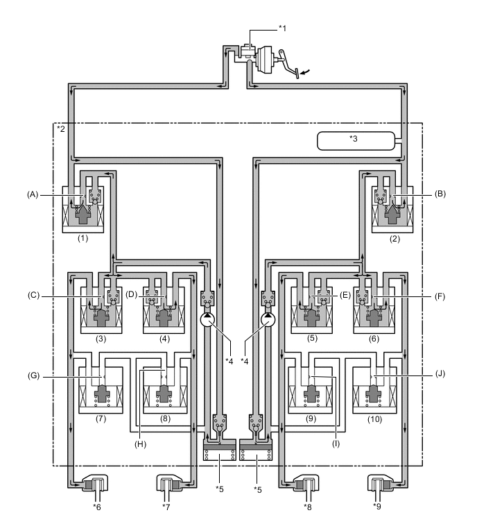
*1 Brake Master Cylinder Sub-assembly *2 Brake Actuator Assembly *3 Master Cylinder Pressure Sensor *4 Pump *5 Reservoir *6 Front Brake Caliper (Right Side) *7 Rear Brake Caliper (Left Side) *8 Rear Brake Caliper (Right Side) *9 Front Brake Caliper (Left Side) - - Item Port Brake Assist Not Activated Brake Assist Activated Master Cylinder Cut Solenoid Valves (1), (2) (A), (B) OFF (Open) ON* Pressure Holding Solenoid Valves (3), (4), (5), (6) (C), (D), (E), (F) OFF (Open) OFF (Open) Pressure Reduction Solenoid Valves (7), (8), (9), (10) (G), (H), (I), (J) OFF (Closed) OFF (Closed) Pump OFF ON *: The solenoid valves continually change between open and closed to adjust the hydraulic pressure according to operating conditions.
-
-
TRC
-
The fluid pressure generated by the pump is regulated by the master cylinder cut solenoid valve to achieve the required pressure. Thus, the brakes for the drive wheels are controlled in the following 3 modes: pressure reduction, pressure holding, and pressure increase modes, to control slippage of the drive wheels.
-
The diagram shows the hydraulic circuit in the pressure increase mode when TRC is activated. The pressure holding solenoid valve and the pressure reduction solenoid valve are turned ON/OFF according to the ABS and EBD operation pattern.
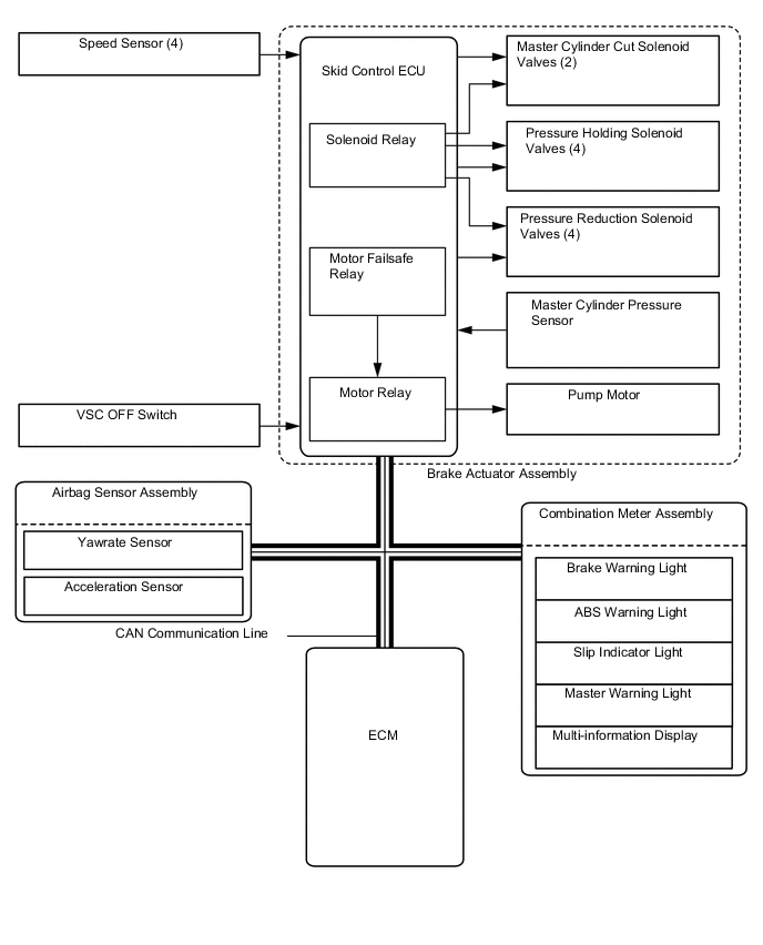
Figure 1. 2WD Models
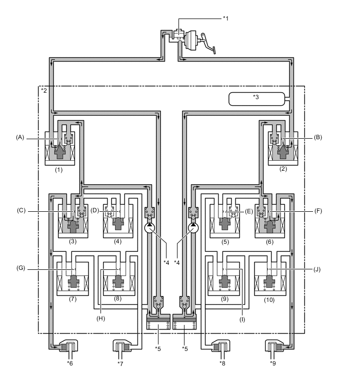
*1 Brake Master Cylinder Sub-assembly *2 Brake Actuator Assembly *3 Master Cylinder Pressure Sensor *4 Pump *5 Reservoir *6 Front Brake Caliper (Right Side) *7 Rear Brake Caliper (Left Side) *8 Rear Brake Caliper (Right Side) *9 Front Brake Caliper (Left Side) - - Item Port TRC Not Activated TRC Activated Increase Mode Holding Mode Reduction Mode Master Cylinder Cut Solenoid Valve (1), (2) (A), (B) OFF (Open) ON* ON* ON* Front Brakes Pressure Holding Solenoid Valve (3), (6) (C), (F) OFF (Open) OFF (Open) ON (Closed) ON (Closed) Pressure Reduction Solenoid Valve (7), (10) (G), (J) OFF (Closed) OFF (Closed) OFF (Closed) ON (Open) Brake Wheel Cylinder Pressure Right - - - Increased Held Reduced Left - - - Increased Held Reduced Rear Brakes Pressure Holding Solenoid Valve (4), (5) (D), (E) OFF (Open) ON (Closed) ON (Closed) ON (Closed) Pressure Reduction Solenoid Valve (8), (9) (H), (I) OFF (Closed) OFF (Closed) OFF (Closed) OFF (Closed) Brake Wheel Cylinder Pressure Right - - - - - - Left - - - - - - Pump OFF ON ON ON *: The solenoid valves continually change between open and closed to adjust the hydraulic pressure according to operating conditions.
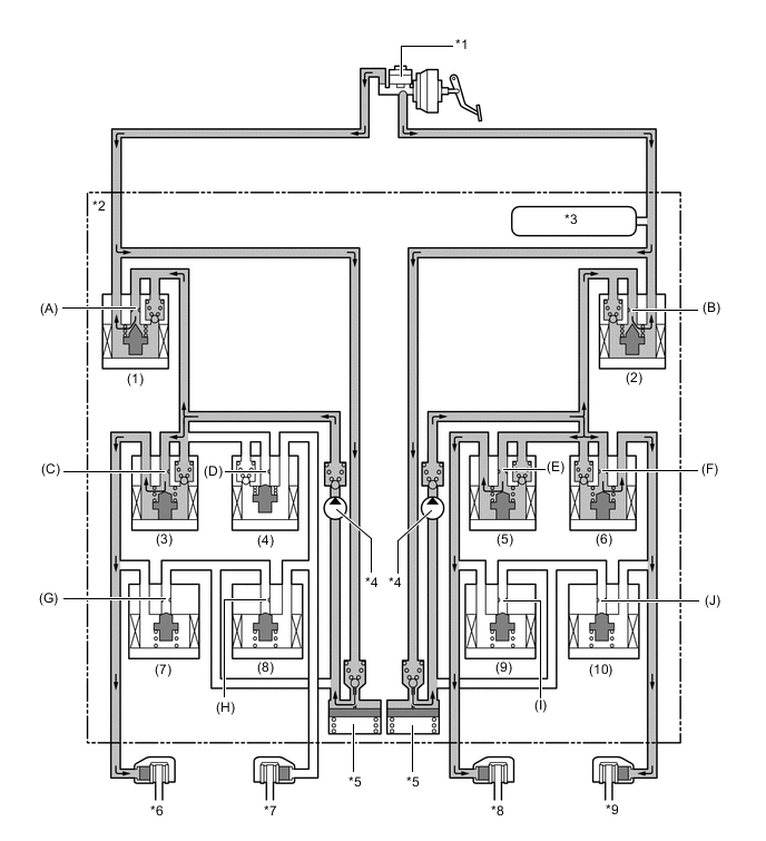
Figure 2. AWD Models

*1 Brake Master Cylinder Sub-assembly *2 Brake Actuator Assembly *3 Master Cylinder Pressure Sensor *4 Pump *5 Reservoir *6 Front Brake Caliper (Right Side) *7 Rear Brake Caliper (Left Side) *8 Rear Brake Caliper (Right Side) *9 Front Brake Caliper (Left Side) - - Item Port TRC Not Activated TRC Activated Increase Mode Holding Mode Reduction Mode Master Cylinder Cut Solenoid Valve (1), (2) (A), (B) OFF (Open) ON* ON* ON* Front Brakes Pressure Holding Solenoid Valve (3), (6) (C), (F) OFF (Open) OFF (Open) ON (Closed) ON (Closed) Pressure Reduction Solenoid Valve (7), (10) (G), (J) OFF (Closed) OFF (Closed) OFF (Closed) ON (Open) Brake Wheel Cylinder Pressure Right - - - Increased Held Reduced Left - - - Increased Held Reduced Rear Brakes Pressure Holding Solenoid Valve (4), (5) (D), (E) OFF (Open) OFF (Open) ON (Closed) ON (Closed) Pressure Reduction Solenoid Valve (8), (9) (H), (I) OFF (Closed) OFF (Closed) OFF (Closed) ON (Open) Brake Wheel Cylinder Pressure Right - - - Increased Held Reduced Left - - - Increased Held Reduced Pump OFF ON ON ON *: The solenoid valves continually change between open and closed to adjust the hydraulic pressure according to operating conditions.
-
-
VSC and TSC
-
VSC, by way of solenoid valves, controls the fluid pressure generated by the pump and applies it to each wheel cylinder in the following 3 modes: pressure reduction, pressure holding, and pressure increase modes. As a result, understeer and oversteer tendencies are controlled.
-
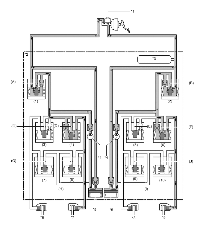
In understeer restraining control, the skid control ECU controls engine output and applies the brakes of both front wheels and the rear wheel on the inside of the turn. Also, depending on whether the brakes are applied and the vehicle condition, there are circumstances in which the brake of a specific wheel may not be applied even if it was targeted for braking. The diagram below shows the hydraulic circuit in the pressure increase mode, as it restrains an understeer tendency while the vehicle is making a right turn. In other operating modes, the pressure holding valve and the pressure reduction valve are turned ON/OFF according to the ABS and EBD operation pattern.
*1 Brake Master Cylinder Sub-assembly *2 Brake Actuator Assembly *3 Master Cylinder Pressure Sensor *4 Pump *5 Reservoir *6 Front Brake Caliper (Right Side) *7 Rear Brake Caliper (Left Side) *8 Rear Brake Caliper (Right Side) *9 Front Brake Caliper (Left Side) - - Item Port VSC Not Activated VSC Activated Increase Mode Holding Mode Reduction Mode Master Cylinder Cut Solenoid Valve (1), (2) (A), (B) OFF (Open ON* ON* ON* Front Brakes Pressure Holding Solenoid Valve (3) (C) OFF (Open) OFF (Open) ON (Closed) ON (Closed) (6) (F) OFF (Open) OFF (Open) ON (Closed) ON (Closed) Pressure Reduction Solenoid Valve (7) (G) OFF (Closed) OFF (Closed) OFF (Closed) ON (Open) (10) (J) OFF (Closed) OFF (Closed) OFF (Closed) ON (Open) Brake Wheel Cylinder Pressure Right - - - Increased Held Reduced Left - - - Increased Held Reduced Rear Brakes Pressure Holding Solenoid Valve (4) (D) OFF (Open) ON (Closed) ON (Closed) ON (Closed) (5) (E) OFF (Open) OFF (Open) ON (Closed) ON (Closed) Pressure Reduction Solenoid Valve (8) (H) OFF (Closed) OFF (Closed) OFF (Closed) OFF (Closed) (9) (I) OFF (Closed) OFF (Closed) OFF (Closed) ON (Open) Brake Wheel Cylinder Pressure Right - - - Increased Held Reduced Left - - - - - - Pump OFF ON ON ON *: The solenoid valves continually change between open and closed to adjust the hydraulic pressure according to operating conditions.
-
In oversteer restraining control, the skid control ECU applies the brakes of the front and rear wheel on the outside of the turn. Also, depending on whether the brakes are applied and the vehicle condition, the brake of a specific wheel may not be applied even if it was targeted for braking. The diagram below shows the hydraulic circuit in the pressure increase mode, as it restrains an oversteer tendency while the vehicle is making a right turn. In other operating modes, the pressure holding valve and the pressure reduction valve are turned ON/OFF according to the ABS and EBD operation patterns.
*1 Brake Master Cylinder Sub-assembly *2 Brake Actuator Assembly *3 Master Cylinder Pressure Sensor *4 Pump *5 Reservoir *6 Front Brake Caliper (Right Side) *7 Rear Brake Caliper (Left Side) *8 Rear Brake Caliper (Right Side) *9 Front Brake Caliper (Left Side) - - Item Port VSC Not Activated VSC Activated Increase Mode Holding Mode Reduction Mode Master Cylinder Cut Solenoid Valve (1), (2) (A), (B) OFF (Open) ON* ON* ON* Front Brakes Pressure Holding Solenoid Valve (3) (C) OFF (Open) ON (Closed) ON (Closed) ON (Closed) (6) (F) OFF (Open) OFF (Open) ON (Closed) ON (Closed) Pressure Reduction Solenoid Valve (7) (G) OFF (Closed) OFF (Closed) OFF (Closed) OFF (Closed) (10) (J) OFF (Closed) OFF (Closed) OFF (Closed) ON (Open) Brake Wheel Cylinder Pressure Right - - - - - - Left - - - Increased Held Reduced Rear Brakes Pressure Holding Solenoid Valve (4) (D) OFF (Open) OFF (Open) ON (Closed) ON (Closed) (5) (E) OFF (Open) ON (Closed) ON (Closed) ON (Closed) Pressure Reduction Solenoid Valve (8) (H) OFF (Closed) OFF (Closed) OFF (Closed) ON (Open) (9) (I) OFF (Closed) OFF (Closed) OFF (Closed) OFF (Closed) Brake Wheel Cylinder Pressure Right - - - - - - Left - - - Increased Held Reduced Pump OFF ON ON ON *: The solenoid valves continually change between open and closed to adjust the hydraulic pressure according to operating conditions.
-
-
VSC and Cooperative Control with EPS
-
The operation of the solenoid valves under the steering cooperative control is the same as the TRC or VSC operation.
-
-
Hill-start Assist Control
-
The skid control ECU determines the starting of the hill-start assist control operation in accordance with information provided by various sensors, switches and the ECM. At this time, the skid control ECU controls the fluid pressure and applies it by way of the solenoid valves to the brake wheel cylinder of each wheel in the following 2 modes: pressure reduction and pressure holding modes.
-
The skid control ECU computes that the vehicle is in a state in which the hill-start assist control can start operating in accordance with the signals provided by the speed sensors, yaw rate and deceleration sensor, stop light switch assembly, accelerator pedal sensor assembly and parking brake switch assembly.
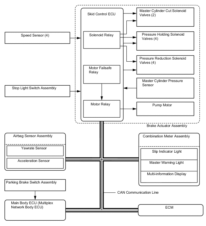
Figure 3. Example of Hill-start Assist Control when Climbing Uphill with Shift Lever in D (Driver Depresses Accelerator Pedal to Start Off after Hill-start Assist Control Operation)
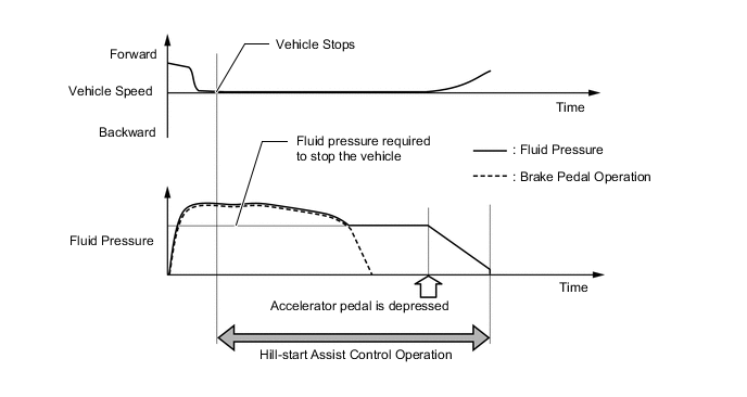
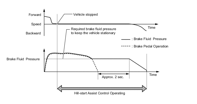
Figure 4. Example of Hill-start Assist Control when Climbing Uphill with Shift Lever in D (Driver Takes No Action after Hill-start Assist Control Operation)
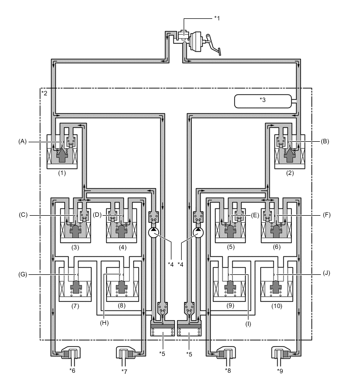
*1 Brake Master Cylinder Sub-assembly *2 Brake Actuator Assembly *3 Master Cylinder Pressure Sensor *4 Pump *5 Reservoir *6 Front Brake Caliper (Right Side) *7 Rear Brake Caliper (Left Side) *8 Rear Brake Caliper (Right Side) *9 Front Brake Caliper (Left Side) - - Item Port Hill-start Assist control Not Activated Hill-start Assist Control Activated Holding Mode Reduction Mode Master Cylinder Cut Solenoid Valve (1), (2) (A), (B) OFF (Open) ON* ON* Front Brakes Pressure Holding Solenoid Valve (3), (6) (C), (F) OFF (Open) OFF (Open) OFF (Open) Pressure Reduction Solenoid Valve (7), (10) (G), (J) OFF (Closed) OFF (Closed) OFF (Closed) Brake Wheel Cylinder Pressure Right - - - Held Reduced Left - - - Held Reduced Rear Brakes Pressure Holding Solenoid Valve (4), (5) (D), (E) OFF (Open) OFF (Open) OFF (Open) Pressure Reduction Solenoid Valve (8), (9) (H), (I) OFF (Closed) OFF (Closed) OFF (Closed) Brake Wheel Cylinder Pressure Right - - - Held Reduced Left - - - Held Reduced Pump OFF ON ON *: The solenoid valves continually change between open and closed to adjust the hydraulic pressure according to operating conditions.
-
-
Downhill Assist Control
-
Based on the information provided by various sensors, switches and the ECM, the skid control ECU determines the conditions that enable the downhill assist control operation. Then, the skid control ECU controls the fluid pressure that is generated by the pump and applies it by way of the solenoid valve to the brake wheel cylinder of each wheel in the following 3 modes: pressure reduction, pressure holding and pressure increase modes.
-
The skid control ECU computes the vehicle speed, travel direction and the gradient of the hill in accordance with the signals that are input by the speed sensor and the yaw rate and deceleration sensor, and performs brake control to attain the target vehicle speed. The target vehicle speed is determined by the direction of the vehicle.
Travel Direction Forward Backward Target Vehicle Speed km/h (mph) 4 to 8 (3 to 5) 4 to 7 (3 to 4) -
When the driver increases the vehicle speed by depressing the accelerator or decreases the vehicle speed by depressing the brake pedal, downhill assist control maintains the vehicle speed within the specified speed range.
-
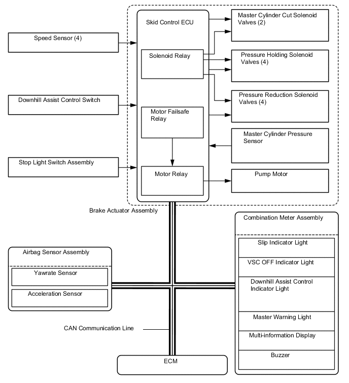
During the downhill assist control operation, the skid control ECU outputs signals to the stop light control relay assembly to cause the stop lights to turn on and to the combination meter assembly to cause the slip indicator light to blink.
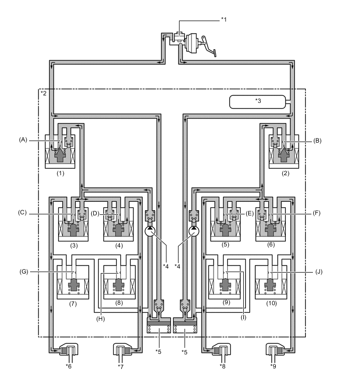
*1 Brake Master Cylinder Sub-assembly *2 Brake Actuator Assembly *3 Master Cylinder Pressure Sensor *4 Pump *5 Reservoir *6 Front Brake Caliper (Right Side) *7 Rear Brake Caliper (Left Side) *8 Rear Brake Caliper (Right Side) *9 Front Brake Caliper (Left Side) - - Item Port Downhill Assist Control Not Activated Downhill Assist Control Activated Increase Mode Holding Mode Reduction Mode Master Cylinder Cut Solenoid Valve (1), (2) (A), (B) OFF (Open) ON* ON* ON* Front Brakes Pressure Holding Solenoid Valve (3), (6) (C), (F) OFF (Open) OFF (Open) ON (Closed) ON (Closed) Pressure Reduction Solenoid Valve (7), (10) (G), (J) OFF (Closed) OFF (Closed) OFF (Closed) ON (Open) Brake Wheel Cylinder Pressure Right - - - Increased Held Reduced Left - - - Increased Held Reduced Rear Brakes Pressure Holding Solenoid Valve (4), (5) (D), (E) OFF (Open) OFF (Open) ON (Closed) ON (Closed) Pressure Reduction Solenoid Valve (8), (9) (H), (I) OFF (Closed) OFF (Closed) OFF (Closed) ON (Open) Brake Wheel Cylinder Pressure Right - - - Increased Held Reduced Left - - - Increased Held Reduced Pump OFF ON ON ON *: The solenoid valves continually change between open and closed to adjust the hydraulic pressure according to operating conditions.
-
-
Radar Cruise Control Brake
-
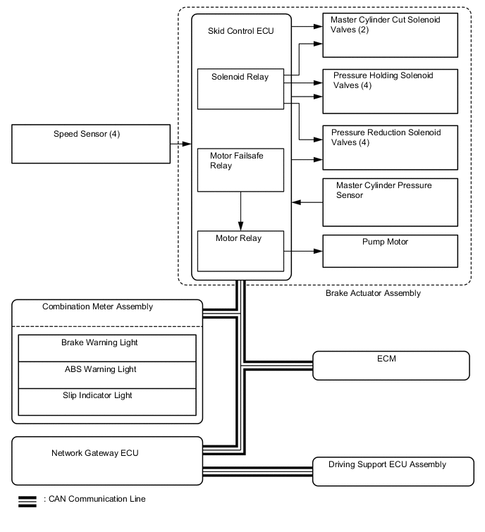
The skid control ECU operates the brakes by receiving a motive force request signal from the driving support ECU assembly while the dynamic radar cruise control system is being activated. This brake control operates in the same way as the normal brake operation.
-
-
Pre-collision Brake
-
If the driving support ECU assembly determines that the possibility of a collision is high, the ECU sends the pre-collision brake assist request signal to the skid control ECU. Upon receiving the signal, the skid control ECU switches the brake assist to standby mode. When the driver depresses the brake pedal, the skid control ECU operates the brake assist based on the master cylinder pressure sensor.
-
If a collision is unavoidable, the skid control ECU actuates the motor in the power supply portion to apply direct pressure to the wheel cylinders even if the driver does not depress the brake pedal. This brake control operates in the same way as the normal brake operation.
-
-