DYNAMIC TORQUE CONTROL AWD SYSTEM
-
FUNCTION OF MAIN COMPONENTS
Component Function Transfer Drive force input into the differential is redirected 90 degrees and output to the propeller shaft by the transfer. Electro Magnetic Control Coupling Sub-assembly Electromagnetic Solenoid Distributes drive torque in accordance with the amperage applied by the 4WD ECU assembly. Throttle Body with Motor Assembly Throttle Position Sensor Detects the throttle valve position and outputs it to the ECM. Crank Position Sensor Detects the engine speed and outputs it to the ECM. Speed Sensor Detects the wheel speed of each wheel. Steering Sensor Detects the direction and angle of the steering wheel. Park/Neutral Position Switch Assembly Detects the shift position of the transaxle and outputs it to the ECM. Stop Light Switch Assembly Detects when the brake pedal is depressed. Parking Brake Switch Assembly Detects when the parking brake is applied. Differential Lock Switch Switches to LOCK mode. 4WD ECU Assembly
-
Controls the amperage applied to the electromagnetic solenoid based on signals provided by the ECUs, sensors and switches in order to optimally distribute drive torque in accordance with driving conditions.
-
Turns AWD mode off when a parking brake ON signal is received from the main body ECU (multiplex network body ECU).
-
Turns AWD mode off when a shift position signal (P or N) is received from the ECM.
ECM Outputs signals such as the shift position signal, throttle position signal and engine speed signal to the 4WD ECU assembly. Brake Actuator Assembly Skid Control ECU Outputs signals such as the vehicle speed signal and deceleration signal to the 4WD ECU assembly. Airbag Sensor Assembly Yawrate Sensor Detects the vehicle's yaw rate, longitudinal and lateral acceleration and deceleration. Acceleration Sensor Main Body ECU (Multiplex Network Body ECU) Outputs signals such as the parking brake signal to the 4WD ECU assembly. Combination Meter Assembly Multi-information Display
-
Displays a warning message to inform or warn the driver of the system condition in accordance with signals from the 4WD ECU assembly.
-
Displays the distribution of drive torque to the front and rear wheels by the AWD system.*
Master Warning Light Illuminates to warn the driver if a malfunction occurs in the AWD system. Differential Lock Indicator Light Illuminates to inform the driver that AWD lock mode is engaged. Buzzer Warns the driver by sounding when a message is shown on the multi-information display. *: Models with color type multi-information display
-
-
SYSTEM CONTROL
-
AWD Control
-
Starting Off
-
The system ensures start-off performance by optimally distributing engine drive torque to the front and rear wheels.
-
To prevent the tight corner braking phenomenon from occurring during low-speed cornering, the system reduces the amount of torque distributed to the rear wheels.
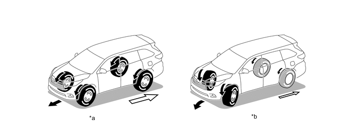
*a Straightline Driving *b Low-speed Cornering 
Torque Distribution to Rear Wheels - -
-
-
Normal Driving
-
During normal driving, when the system judges that the vehicle is traveling steadily, it reduces the amount of torque distribution to the rear wheels. This allows the vehicle to operate in conditions similar to front-wheel-drive, improving fuel economy.
-
The system optimizes torque distribution to the rear wheels to ensure both excellent straightline acceleration performance and excellent driving stability while cornering.
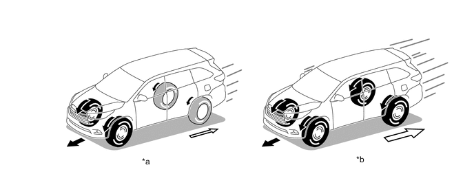
*a Steady Driving *b Straightline Acceleration Torque Distribution to Rear Wheels - -
-
-
-
AWD Control in LOCK Mode
-
When the vehicle is being driven in gravel or sand and more traction is required, the driver can select Lock mode by operating the differential lock switch. Thus, this mode achieves optimal control in accordance with the driving conditions and transmits as much drive torque as possible to the rear wheels, in a mode that is similar to the locked AWD mode.
-
-
Engine Output Control
-
If there is a possibility that overdriving could damage the powertrain system, engine output may be restricted.
-
-
-
FUNCTION
-
AWD Operation Condition Display (Models with Color Type Multi-information Display)
-
The operation conditions of the AWD system, which automatically operates according to the longitudinal and lateral g-force and steering angle while the vehicle is being driven, are displayed on the multi-information display.
-
With this display, even on a slippery road, the user can monitor the condition of the AWD control system as it operates in accordance with the surrounding conditions. This contributes to an improved feeling of safety provided by AWD systems.
-
AWD operation condition display mode can be enabled or disabled by operating the steering pad switch assembly.
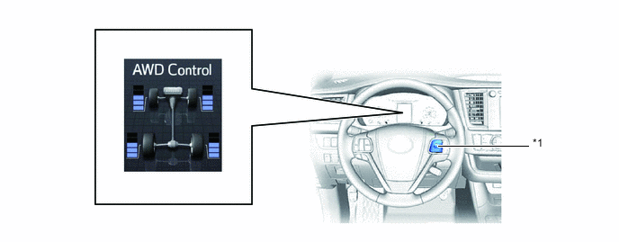
*1 Steering Pad Switch Assembly - - -
AWD Display
-
The ratio of drive torque distributed to the front and rear wheels varies according to driving conditions.
-
The drive torque distributed to each of the front and rear wheels is displayed using segments. If the drive torque is large, more segments are illuminated. If the drive torque is small, less segments are illuminated.
-
When the drive torque to the rear wheels is large, the AWD system judges that more stability and roadholding performance is required and AWD control is engaged.
-
When the drive torque to the rear wheels is small, the AWD system judges that the vehicle is being driven stably and AWD control is suppressed for improved fuel efficiency.
-
-
-
-
FAIL-SAFE
-
When there is a possibility of causing damage to the drivetrain due to a malfunction in the AWD system or rough driving, the system illuminates or blinks the master warning light, displays a warning message on the multi-information display to inform the driver and interrupts AWD control.
Condition Master Warning Light Multi-information Display AWD system malfunction Illuminates CHECK AWD SYSTEM Rough driving in AWD mode Pre-warning for interrupting AWD control Blinks AWD system overheated. Switching to 2WD mode. Interrupting AWD control Blinks AWD system overheated. 2WD mode engaged. Tech Tips
When the 4WD ECU assembly judges that the vehicle has stabilized, it resumes AWD mode. If the master warning light blinks and displays a warning message on the multi-information display, take the following actions without turning the engine off:
-
Decelerate the vehicle until the light goes out.
-
Stop the vehicle and wait until the light goes out.
-
-
-
DIAGNOSIS
-
Furthermore, the master warning light in the combination meter assembly will illuminate and a warning message will be displayed on the multi-information display to inform the driver.
-
For details of the DTCs that are stored in 4WD ECU assembly memory, refer to the Repair Manual.
-