ENGINE UNIT
-
CONSTRUCTION
-
Each cylinder of this engine has 2 intake valves and 2 exhaust valves. Intake and exhaust efficiency is increased due to larger total port areas.
-
This engine uses roller rocker arms with built-in needle bearings. This reduces the friction that occurs between the cams and the roller rocker arms when the valves are pushed down, thus improving fuel economy.
-
Valve lash adjuster assemblies, which maintain a constant zero valve clearance through the use of oil pressure and spring force, are used.
-
The intake camshafts are driven by the crankshaft via the primary timing chain. The exhaust camshafts are each driven by the intake camshaft of their respective bank via a secondary chain.
-
This engine has the Dual Variable Valve Timing-intelligent (VVT-i) system which controls the intake camshafts and exhaust camshafts to provide optimal valve timing according to driving conditions. With this adoption, lower fuel consumption, higher engine performance, and fewer exhaust emissions have been achieved. For details, refer to the Dual VVT-i control.
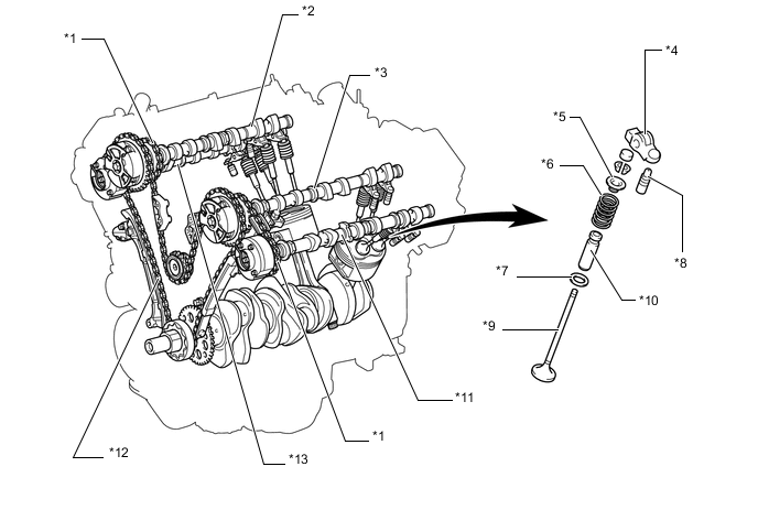
*1 No. 2 Chain Sub-assembly (Secondary) *2 Camshaft (RH, Intake) *3 No. 3 Camshaft Sub-assembly (LH, Intake) *4 No. 1 Valve Rocker Arm Sub-assembly *5 Valve Spring Retainer *6 Compression Spring *7 Valve Spring Seat *8 Valve Lash Adjuster Assembly *9 Valve *10 Valve Guide Bush *11 No. 4 Camshaft Sub-assembly (LH, Exhaust) *12 Chain Sub-assembly (Primary) *13 No. 2 Camshaft (RH, Exhaust) - - Valve Timing Intake Valve Open -3° to 37° BTDC Close 71° to 31° ABDC Exhaust Valve Open 60° to 25° BBDC Close 4° to 39° ATDC 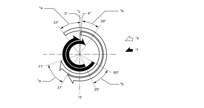
*a Intake VVT-i Operation Range *b Exhaust VVT-i Operation Range *c TDC *d BDC *e Intake Valve Operation Angle *f Exhaust Valve Operation Angle
-