ENGINE UNIT
-
CONSTRUCTION
-
The ventilation hose, No. 2 ventilation hose and ventilation valve sub-assembly are used for blow-by gas ventilation control. Blow-by gas with a large quantity of hydrocarbons is prevented from being discharged into the atmosphere by directing the blow-by gas into the intake system and combusting the gas. A new reflux flow system has been adopted to intake fresh air from the air cleaner hose assembly via the cylinder head cover sub-assembly and to direct blow-by gas to the intake air surge tank assembly via the cylinder head cover sub-assembly.
-
During light engine loads, blow-by gas is suctioned through the ventilation valve sub-assembly into the intake manifold and will be combusted. Fresh air is pulled into the crank case via the cylinder head cover sub-assembly in order to balance the crank case pressure.
-
During high engine loads, blow-by gas is forced through the ventilation valve sub-assembly and No. 2 ventilation hose into the intake manifold and will be combusted.
-
Blow-by gas is channeled through the cylinder block sub-assembly, cylinder head sub-assembly and cylinder head LH and excellent oil separation and a reduction in oil loss via the blow-by gas is achieved.
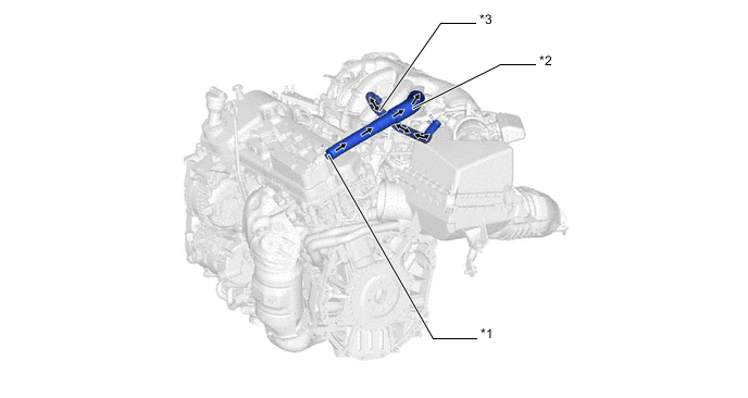
*1 Ventilation Valve Sub-assembly *2 Ventilation Hose *3 No. 2 Ventilation Hose - - Figure 1. PCV Passage Diagram
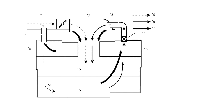
*1 Air Cleaner Hose Assembly *2 Intake Air Surge Tank Assembly *3 Ventilation Hose *4 No. 2 Ventilation Hose *5 Cylinder Block Sub-assembly *6 Oil Pan Sub-assembly *7 Ventilation Valve Sub-assembly - - *a Bank 1 *b Bank 2 *c Fresh Air (Low Engine Loads) *d Fresh Air *e Blow-by Gas *f Blow-by Gas (High Engine Loads)
-