ENGINE UNIT
-
CONSTRUCTION
-
A high-expansion cycle (Atkinson cycle) is used to improve heat efficiency.
-
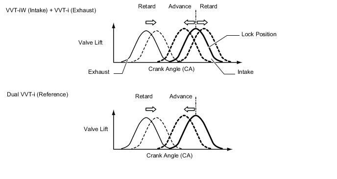
On the intake side, Variable Valve Timing-intelligent Wide (VVT-iW), which is provided with an intermediate lock mechanism that optimally controls the intake camshaft (camshaft and No. 3 Camshaft Sub-assembly) to the valve timings according to driving conditions, is used.
-
On the exhaust side, Variable Valve Timing-intelligent (VVT-i), which optimally controls the exhaust camshaft (No. 2 camshaft and No. 4 Camshaft Sub-assembly) to the valve timings according to driving conditions, is used.
Figure 1. Valve Timing Variable Range
-
A timing rotor for the camshaft position sensor is provided at each the intake and exhaust camshafts.
-
The No. 1 valve rocker arm sub-assembly is used as a valve mechanism and by achieving size reduction while drastically reducing the amount of friction that occurs between the sliding parts and cams, low fuel consumption is achieved. Also, an oil pressure type valve lash adjuster assembly is used to make valve clearance adjustment unnecessary in consideration of serviceability.
-
The cam that drives the fuel pump assembly (for high pressure) is positioned directly above the exhaust camshaft on the right bank to achieve size reduction. Also, a pump cam with 3 peaks is used in the cam that drives the fuel pump assembly (for high pressure) and by synchronizing fuel pressure-feeding and fuel injection, the difference in fuel pressure between cylinders is reduced.
-
The vacuum pump assembly is driven by the end of the intake camshaft on the right bank.
-
A valve spring (inner compression spring), whose upper portion is shaped like a beehive, is used to reduce inertial mass. As a result, the load on the valve spring (inner compression spring) and friction are reduced.
-
The diameter of the valve spring retainer has been decreased to reduce inertial mass and friction.
-
The intake camshafts are driven by the crankshaft via the primary timing chain. The exhaust camshafts are each driven by the intake camshaft of their respective bank via a secondary chain.
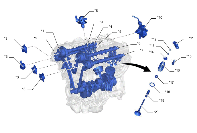
*1 Camshaft Timing Gear Assembly *2 Camshaft Timing Exhaust Gear Assembly *3 Cam Timing Oil Control Solenoid Assembly *4 Intake Camshaft (Camshaft) *5 Exhaust Camshaft (No. 2 Camshaft) *6 Intake Camshaft (No. 3 Camshaft Sub-assembly) *7 Exhaust Camshaft (No. 4 Camshaft Sub-assembly) *8 Fuel Pump Assembly (for High Pressure) *9 Fuel Pump Assembly (for High Pressure) Driving Cam *10 Vacuum Pump Assembly *11 No. 1 Valve Rocker Arm Sub-assembly *12 Valve Stem Cap *13 Valve Spring Retainer Lock *14 Valve Spring Retainer *15 Valve Lash Adjuster Assembly *16 Valve Spring (Inner Compression Spring) *17 Valve Stem Oil Seal *18 Valve Spring Seat *19 Valve Guide Bushing *20 Valve Figure 2. Valve Timing
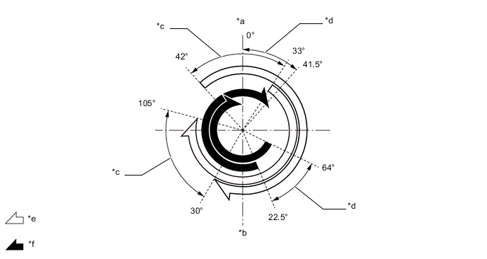
*a TDC *b BDC *c VVT-iW Operation Range *d VVT-i Operation Range *e Intake valve opening angle *f Exhaust valve opening angle
-