BODY STRUCTURE
-
CONSTRUCTION
-
Along with the use of high-tensile strength sheet steel for the windshield header panel inner, the back window frame and upper back window frame inner are structured with closed cross-sections, thus ensuring superior roof strength.
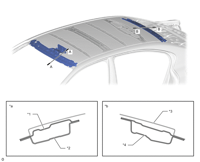
*1 Windshield Header Panel Outer *2 Windshield Header Panel Inner *3 Upper Back Window Frame Inner *4 Back Window Frame *a A-A Cross Section *b B-B Cross Section -
A front pillar door opening gusset upper, which connects the apron member portion and the front pillar portion, is provided in the front fender portion. As a result, a superior steering feel and roll feeling are ensured. In addition, to avoid preventing collision safety, a bead shape is provided for a structure which is easily deformable in a collision.
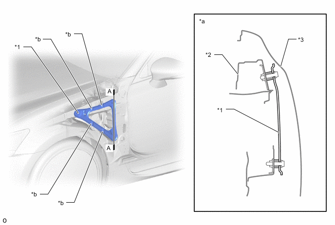
*1 Front Pillar Door Opening Gusset Upper *2 Cowl Top Side Panel Inner *3 Front Fender Panel - - *a A-A Cross Section *b Bead -
The No. 3 center floor reinforcement is located so as to connect the right and left of the front side installation portion of the rear suspension member sub-assembly in a straight line, thus ensuring a high level of rigidity at the load point. As a result, superior maneuvering stability has been achieved.
-
Spot welding points between the front center floor pan and center floor pan, the No. 2 center floor cross member and center floor pan and the No. 1 rear floor cross member and center floor pan are optimally positioned, thus achieving superior maneuvering stability.
-
The thickness of the center floor pan has been increased, thus achieving superior maneuvering stability, riding comfort and quietness.
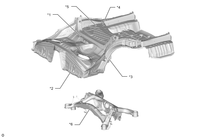
*1 No. 2 Center Floor Cross Member *2 Front Center Floor Pan *3 No. 3 Center Floor Reinforcement *4 No. 1 Rear Floor Cross Member *5 Center Floor Pan *6 Rear Suspension Member Sub-assembly -
The shapes of the radiator support sub-assembly and rear under body have been optimized and each type of brace provided on the under floor has been optimally placed, thus achieving superior maneuvering stability.
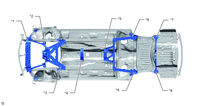
*1 Radiator Support Sub-assembly *2 No. 2 Front Suspension Member Upper *3 Front Suspension Member Brace *4 Engine Rear Mounting Member *5 Front Floor Brace Center *6 Body Mounting Cushion Sub-assembly Rear LH *7 Body Mounting Cushion Sub-assembly Rear RH - - -
The addition of adhesive, LSW (LSW: Laser Spot Welding), laser welding and an increased number of spot welding points has increased the connecting ability of the panels to achieve excellent driving stability (steering response and hand feedback).
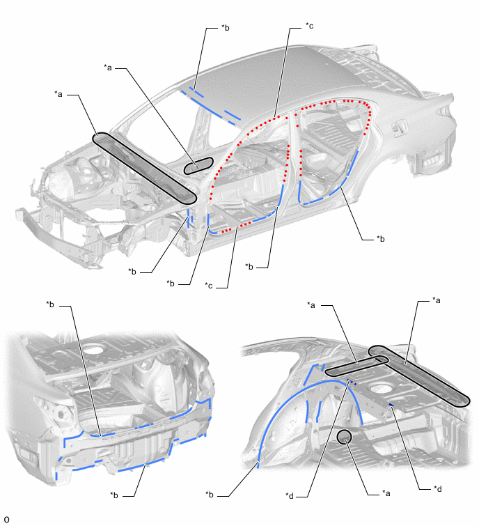
*a Increased Number of Spot Welding Points *b Adhesive *c LSW (Laser Spot Welding) *d Laser Welding
-