BODY STRUCTURE
-
FUNCTION
-
Front Wheel Opening Extension Pad
-
A front wheel opening extension pad is used to reduce the volume of air hitting against the rotating body of the tire. As a result, turbulence generated by the rotation of the front tire which disturbs the surrounding airflow has been suppressed, thus reducing air resistance and achieving a high level of straight-line stability at high speed.
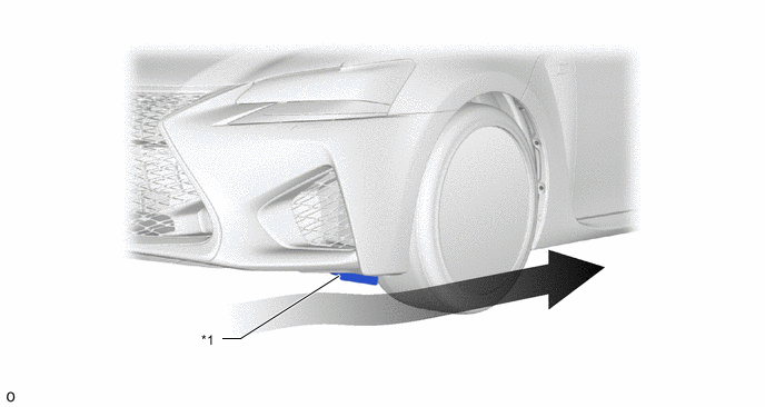
*1 Front Wheel Opening Extension Pad - - 
Airflow - -
-
-
Front Fender Liner
-
A groove is provided in the front fender liner. As a result, air in the wheelhouse flows parallel to the tires and ensures smooth airflow through the wheelhouse, thus achieving superior stability.
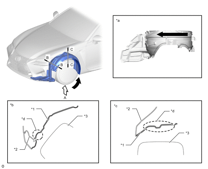
*1 Front Fender Liner *2 Front Fender Panel *3 Front Tire - - *a View from A *b B-B Cross Section *c C-C Cross Section *d Bead Airflow - -
-
-
Rear Floor Housing Shield
-
A rear floor housing shield is used to reduce the volume of air hitting against the rotating body of the tire. As a result, turbulence generated by the rotation of the rear tire which disturbs the surrounding airflow has been suppressed, thus reducing air resistance and achieving a high level of straight-line stability at high speed.
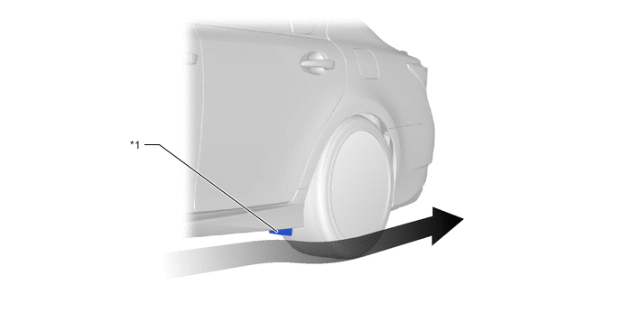
*1 Rear Floor Housing Shield - - Airflow - -
-
-
Rear Wheel House Liner
-
Ridges are provided to direct high-pressure turbulence in the rear wheelhouse caused by the rotation of the rear tire out from the vehicle.
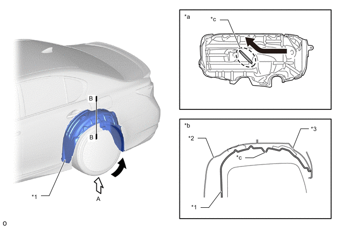
*1 Rear Wheel House Liner *2 Inner Quarter Wheel House Panel *3 Quarter Wheel House Panel Outer - - *a View from A *b B-B Cross Section *c Ridge - - Airflow - -
-
-
Rear Spoiler Sub-assembly
-
The rear spoiler sub-assembly suppresses rearward air vortices, thus aiming for air resistance reduction by smoothing the airflow.
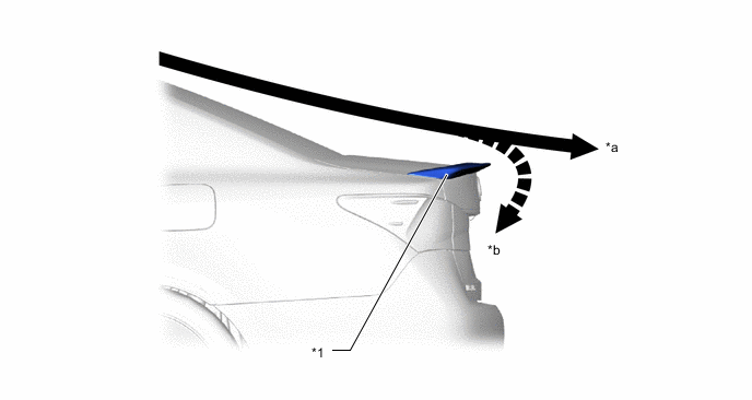
*1 Rear Spoiler Sub-assembly - - *a Airflow *b Vortex
-
-
Aero Stabilizing Fin
-
An edge shape and an aero stabilizing fin are used for the rear combination light assembly. The edge portion cuts and blows airflow rearward to suppress vortices, thus aiming for air resistance reduction by the airflow adjustment effects which flow air smoothly.
-
Aero stabilizing fins (vortex generators) are used for the rear combination light assembly. As air flows over the surfaces of a moving vehicle, friction can cause that air to tumble over and under itself, increasing drag and creating erratic air pressure forces around the vehicle. Aero stabilizing fins alter the airflow before it becomes turbulent, creating a series of controlled spins, or vortices, and helping to equalize air pressure forces, reduce drag and improve vehicle stability.
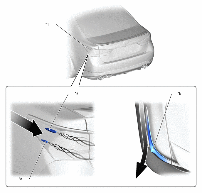
*1 Rear Combination Light Assembly - - *a Aero Stabilizing Fin *b Edge Shape Airflow - -
-
-
Under Body
-
Smooth airflow under the floor of the vehicle enhances the speed of airflow and creates a low pressure region between the vehicle and the road surface (Venturi effect). This low pressure region attracts the vehicle to the road surface, thus causing down force. As a result, superior straight-line stability has been achieved. To create a smooth rearward airflow under the vehicle, the following parts located on the underside of the vehicle are designed to alter the airflow.
-
A flat airflow adjustment surface is provided for the No. 1 engine under cover assembly. Also, aero stabilizing fins are provided.
-
The surface area of the front floor cover and the front floor center cover has been increased, and the height from the ground has also been optimized. In addition, aero stabilizing fins are provided.
-
The under floor cutting angle of the No. 1 floor under cover assembly has been optimized. In addition, aero stabilizing fins are provided.
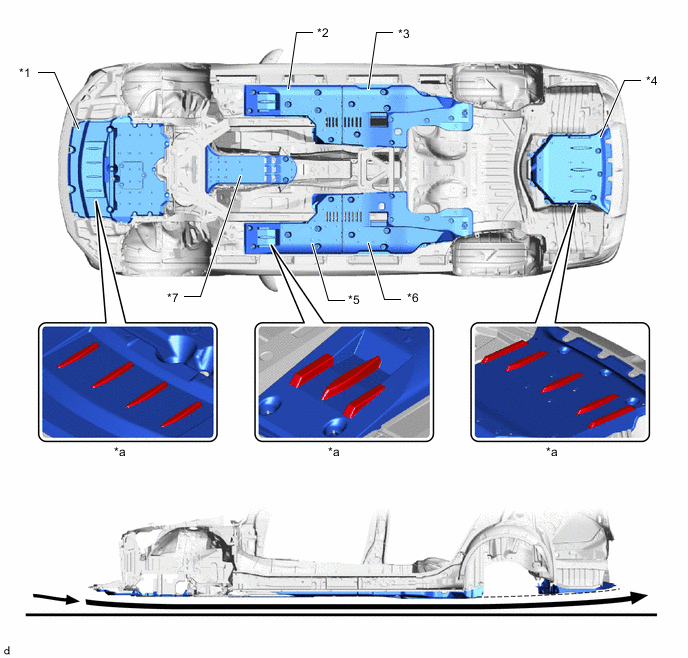
*1 No. 1 Engine Under Cover Assembly *2 Front Floor Cover LH *3 Front Floor Center Cover LH *4 No. 1 Floor Under Cover Assembly *5 Front Floor Cover RH *6 Front Floor Center Cover RH *7 No. 2 Engine Under Cover Assembly - - *a Aero Stabilizing Fin - - Airflow - - -
-
-
Air Outlet
-
Openings have been provided on the hood and fenders to allow air to exit smoothly from the engine compartment thus achieving superior maneuvering stability.
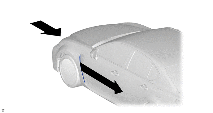
Airflow - -
-
-
Aluminum tape (No. 1 molding tape)
-
Aluminum tape (No. 1 molding tape) is applied to the back surfaces of the front and rear bumper covers. As a result, the electrostatic charge of the bumper covers is reduced to produce a better electrical condition (grounding effect), stabilizing aspects of vehicle performance including driveability and fuel economy.
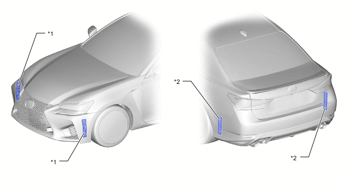
*1 Aluminum tape (No. 1 Molding Tape) *2 Aluminum tape (No. 2 Molding Tape)
-
-