BODY STRUCTURE
-
FUNCTION
-
Impact Absorbing Structure for Frontal Collision
-
A structure that ensures collision energy absorption efficiency, dissipates impact, and minimizes cabin deformation during a frontal collision has been achieved.
-
Ultra high-tensile strength sheet steel (980 MPa class) is used for the No. 1 rocker panel reinforcement. In addition, strengthening reinforcement has been added to the No. 1 rocker panel reinforcement. As a result, deformation of the cabin, which is caused by the pitching of the vehicle in an offset frontal collision, has been suppressed.
-
The rocker front end portion has been extended forward to receive and dissipate collision load transferred from the tires in an offset frontal collision, thus suppressing body deformation on the periphery of the cabin.
-
The front body pillar reinforcement lower and front body pillar reinforcement outer are constructed with an overlap structure that features upper-and-lower separation together to strengthen the front body pillar portion, thus suppressing body deformation (caused by collision load input from the tires in an offset front collision) on the periphery of the cabin.
-
High-tensile strength sheet steel (590 MPa class) is used for the front door inside panel reinforcement. In addition, the longitudinal wall of the front door inside panel reinforcement is located further toward the interior side than the centroid, thus suppressing deformation of the door by compression load in an offset front collision.
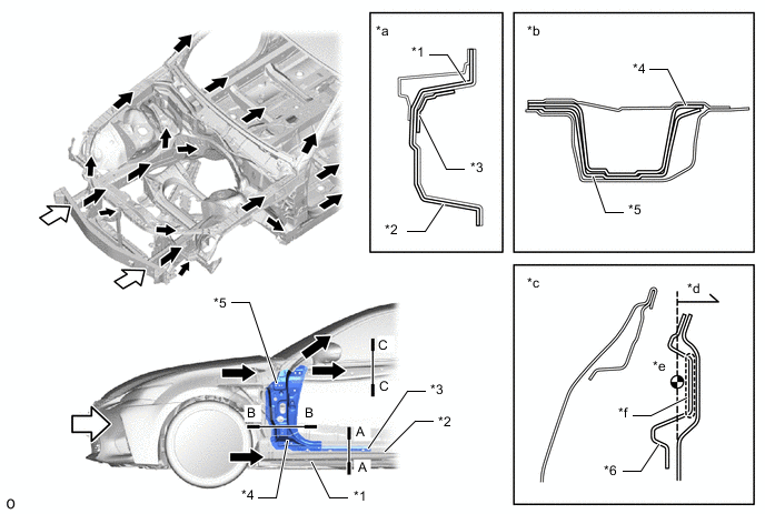
*1 Fender Panel Inner *2 No. 1 Rocker Panel Reinforcement *3 No. 4 Rocker Panel Reinforcement *4 Front Body Pillar Upper Extension Outer *5 Front Body Pillar Reinforcement Lower *6 Front Door Inside Panel Reinforcement *a A-A Cross Section *b B-B Cross Section *c C-C Cross Section *d Interior Side *e Centroid *f Longitudinal Wall 
Impact 
Path to Collision Energy -
-
-
Impact Absorbing Structure for Side Collision
-
A structure that ensures collision energy absorption efficiency, dissipates impact, and minimizes cabin deformation during a side collision has been achieved.
-
Hot-stamped steel (1500 MPa class), ultra high-tensile strength sheet steel (980 MPa class) and high-tensile strength sheet steel (590 MPa class) are used for each body frame part, thus ensuring strength against side collisions and achieving weight reduction and structure simplicity.
Tech Tips
Hot-stamped steel is a highly strengthened material, which is made by forming and cooling heated steel simultaneously and then hardening it.
-
Hot-stamped steel (1500 MPa class) is used for the center body pillar reinforcement upper. In addition, the high-tensile strength sheet steel (590 MPa class) center pillar hinge reinforcement upper is located inside the upper center body pillar reinforcement.
-
Hot-stamped steel (1500 MPa class) is used for the roof side rail.
-
Ultra high-tensile strength sheet steel (980 MPa class) is used for the No. 1 rocker panel reinforcement, and high-tensile strength sheet steel (590 MPa class) is used for the rocker panel sub-assembly outer and No. 3 rocker panel reinforcement, which are inside the No. 1 rocker panel reinforcement. Front-and-rear length has been increased to suppress corruption of the rocker cross-section in a side collision, thus reducing the center body pillar's intrusion into the cabin.
-
High-tensile strength sheet steel (590 MPa class) is used for the center roof panel reinforcement.
-
The thickness of the rear door side impact protection beam has been increased, thus reducing the rear door's intrusion into the cabin in a side collision.
-
A bulkhead (No. 6 rocker panel reinforcement) is added to the No. 5 rocker panel reinforcement. In addition, hard resin reinforcement (rocker panel protector inner rear) is located in the interior side to transfer the rear door side impact protection beam and load, thus suppressing the intrusion of the rear door in a side collision.
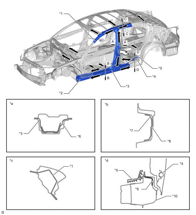
*1 Roof Side Rail *2 No. 1 Rocker Panel Reinforcement *3 Center Body Pillar Reinforcement Sub-assembly *4 Rear Door Side Impact Protection Beam *5 Rocker Panel Protector Inner Rear *6 Center Pillar Hinge Reinforcement Upper *7 Rocker Panel Sub-assembly Outer *8 No. 3 Rocker Panel Reinforcement *9 No. 6 Rocker Panel Reinforcement *10 No. 5 Rocker Panel Reinforcement *a A-A Cross Section *b B-B Cross Section *c C-C Cross Section *d D-D Cross Section Impact Path of Collision Energy
-
Collision load input from the center body pillar in a side collision is transferred either to the box support bracket installed on the front floor pad or its upper portion through the front floor cross member reinforcement sub-assembly, front seat adjuster assembly and connecting rod. As a result, the diffusion of collision load has been optimized to reduce the deformation amount of the body in a side collision.
-
A front door stiffener cushion is provided inside the door panel to enhance the transmission efficiency of collision load, thus aiming for a reduction of the injury criterion level.
-
The front door trim pad lower is provided in the front door trim board sub-assembly to reduce collision load toward the passengers in a side collision, thus aiming for a reduction of the injury criterion level.
-
The position, shape and rigidity of the front door trim board sub-assembly shoulder portion and the front door armrest assembly have been optimized to reduce collision load toward the driver and front passengers in a side collision, thus aiming for a reduction of the injury criterion level.
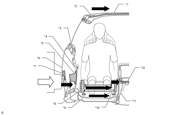
*1 Roof Panel Reinforcement Center *2 Roof Panel Reinforcement *3 Front Door Armrest Assembly *4 Front Door Trim Board Sub-assembly *5 Front Door Trim Pad Lower *6 Front Door Panel Outer *7 No. 1 Front Door Stiffener Cushion *8 Front Seat Adjuster Assembly *9 Front Floor Crossmember Reinforcement Sub-assembly *10 Connecting Rod *11 Front Floor Pad *12 Box Support Bracket Impact Path of Collision Energy
-
-
-
Lessening Pedestrian Head Injury
-
In the case of a collision with a pedestrian, pedestrian injury reduction is taken into consideration by the use of pedestrian injury reduction body. An impact absorbing body structure is used on the periphery of the hood panel and cowl top panel, thus achieving a body structure which reduces impact to the pedestrian's head, etc.
-
A structure which is easily bent is used for the front fender protector upper. If a pedestrian's head, etc. collides with the hood sub-assembly, the front fender protector upper bends to reduce opposed reaction force from the hood sub-assembly to the head etc., thus aiming for a reduction of impact against a pedestrian.
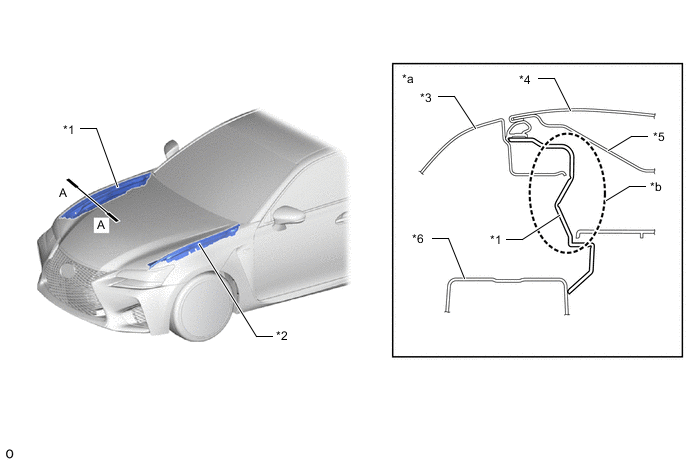
*1 Front Fender Protector Upper RH *2 Front Fender Protector Upper LH *3 Front Fender Panel *4 Hood Panel *5 Hood Panel Inner *6 Front Apron to Cowl Side Member Upper RH *a A-A Cross Section *b Structure which can be Easily Bent -
A vertical bead structure is used for the hood panel inner, thus aiming for a reduction of impact against the pedestrian's head, etc. in a collision with a pedestrian. In addition, the height and pitch of the beads have been optimized, thus achieving a slim hood sub-assembly structure while maintaining impact reduction performance.
-
Bead shapes which can form bending base points are provided at the end of the hood panel inner. As a result, the structure bends to deform easily at base points created by the ledge end of the hood panel inner and the beads next to the hood lock hook base when the pedestrian's thigh area collides with the hood end, thus aiming for a reduction of impact against the pedestrian's thigh area.
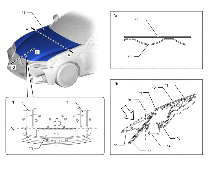
*1 Hood Sub-assembly *2 Hood Panel *3 Hood Panel Inner *4 Hood Lock Hook Sub-assembly *5 Hood Lock Hook Base - - *a A-A Cross Section *b B-B Cross Section *c Fold Line *d Before Collision *e After Impact Absorption *f Bead *g Ledge - - Impact - - -
For the hood hinge assembly, a crushable structure is used for the hood hinge outer bracket plate to achieve a construction which can be crushed easily. As a result, reduction of the impact against a pedestrian has been aimed for in a collision with a pedestrian.
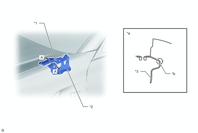
*1 Hood Hinge Assembly LH *2 Hood Hinge Bracket LH *3 Hood Hinge Outer Bracket Plate LH - - *a A-A Cross Section *b Crushable Structure -
The following shape is used for the cowl top ventilator louver sub-assembly, thus maintaining necessary rigidity and aiming for a reduction of impact against a pedestrian in a collision with a pedestrian.
-
The line of the hood to cowl top seal has been made flat and smooth, thus achieving a structure which can deform easily.
-
Both sides of the cowl top ventilator louver sub-assembly have been made open, thus achieving a structure which can deform easily.
-
A thin-walled portion is provided to control deformation by creating deformation points.
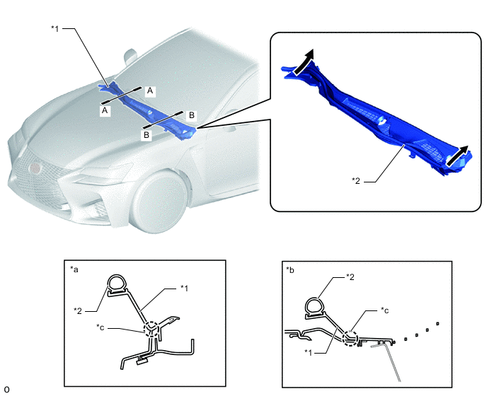
*1 Cowl Top Ventilator Louver Sub-assembly *2 Hood to Cowl Top Seal *a A-A Cross Section *b B-B Cross Section *c Thin-walled Portion (Deformation Point) - - Open Structure - - -
By providing fold points on the front cowl top panel outer and by making the structure easily crushable, energy coming from the expected direction in a head area collision is more effectively absorbed, and a structure which reduces the remaining areas which are not completely crushed has been achieved. As a result, impact against the head area, etc. is reduced in a collision with a pedestrian.
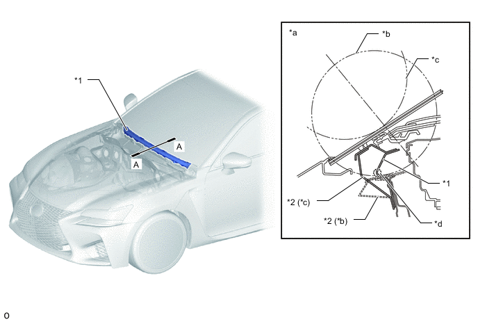
*1 Front Cowl Top Panel Outer *2 No. 1 Wiper Motor Mounting Bracket *a A-A Cross Section *b After Collision *c Before Collision *d Fold Point
-
-
-