LIGHTING SYSTEM
-
FUNCTION OF MAIN COMPONENTS
*: Models with camera heaterComponent Function Integration Control and Panel Assembly Adaptive High-beam System Switch Outputs the switch on signal to the headlight light control ECU sub-assembly LH. Forward Recognition Camera (Camera Sensor)
-
Identifies a preceding vehicle, oncoming vehicle, and streetlights based on an image captured by the camera, and sends the position information of the preceding and oncoming vehicles via CAN communication to headlight light control ECU sub-assembly LH and RH.
-
Transmits an operation signal to the camera heater.*
Camera Heater (Forward Recognition Hood with Heater Sub-assembly)* Heats the sheet heater in accordance with the signals from the forward recognition camera (camera sensor). Millimeter Wave Radar Sensor Assembly Emits millimeter waveband radio waves forward, receives the radio waves reflected by objects in front of the vehicle, and calculates the distances, directions and relative speeds of the objects. Main Body ECU (Multiplex Network Body ECU) Receives each sensor and switch condition and illuminates or turns off the lights. ECM The ECM sends a vehicle information signal via the CAN communication to the headlight light control ECU sub-assembly LH. Brake Actuator Assembly Skid Control ECU Sends the vehicle speed signal to the headlight control ECU sub-assembly LH. Headlight Assembly LH/RH Headlight Light Control ECU Sub-assembly LH/RH
-
Outputs a request signal to the combination meter assembly to illuminate the adaptive high beam indicator light or high beam indicator light in accordance with the system operating conditions.
-
When an abnormal condition occurs in the adaptive high beam control system, Diagnostic Trouble Codes (DTCs) are stored in memory.
LED Light Control Computer LH/RH Receives signals from the headlight light control ECU sub-assembly and adjusts the light distribution pattern of the headlights in accordance with the vehicle and surrounding conditions. Headlight Leveling Motor LH/RH Adjusts the vertical orientations of the headlights based on the control signals from the headlight light control ECU sub-assembly LH and RH to adjust the optical axis of the headlights. Combination Meter Assembly Adaptive High beam Indicator Light Illuminates when the adaptive high beam system is operated. Headlight High Beam Indicator Light Illuminates when the high beams are on. Master Warning Light Illuminates when an abnormal condition occurs in the adaptive high beam system. Multi-information Display Displays a warning message when an abnormal condition occurs in the adaptive high beam system. Automatic Light Control Sensor Detects the ambient light level and outputs signals to the main body ECU (multiplex network body ECU). Rear Height Control Sensor Subassembly LH Detects the amount of variance of the vehicle height and outputs this amount in the form of signals to the headlight light control ECU sub-assembly LH.
-
-
SYSTEM CONTROL
-
The adaptive high beam system operates as follows:
-
When all of the following conditions are met, the adaptive high beam system is activated and the adaptive high beam indicator light automatically turns on.
-
The engine switch is on (IG).
-
The light control switch (headlight dimmer switch assembly) is in the HEAD or AUTO position and the low beam headlights are on.
-
The dimmer switch (headlight dimmer switch assembly) is in the high beam position.
-
The adaptive high-beam system switch is on*1
-
The vehicle speed is approximately 15 km/h (10 mph) or more.*2
-
The vehicle speed is approximately 60 km/h (38 mph) or more.*3
Tech Tips
*1: When the adaptive high-beam system switch is turned on while the headlights are off or the dimmer switch (headlight dimmer switch assembly) is in any position other than the high beam position, a message "To Activate AHS, Switch Headlights to High Beam" will be displayed on the multi information display in the combination meter assembly.
*2: Except models for Europe
*3: Models for Europe
-
-
-
-
FUNCTION
-
Variable High Beam Light Distribution Control System:
-
The variable high beam light distribution control system controls the illumination intensity and irradiation area of the high beams.
-
The illumination intensity and irradiation areas are switched in 3 levels.
Illumination Mode Description of Function Vehicle Speed Low Speed Mode (Town Mode)
-
Widens the illuminated area.
-
The brightness of the headlights is adjusted to ensure that pedestrians are visible while not being dazzled.
-
Reduces illumination of the side of the road.
-
15 - 30 km/h
(10 - 19 mph)*1
-
-*2
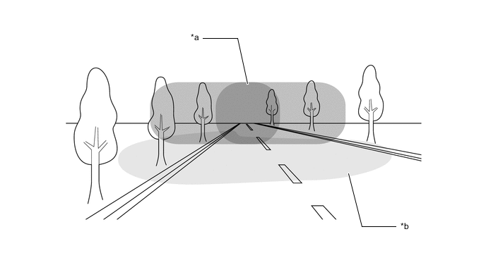
Normal Mode
-
At medium speeds, the illuminated area in front of the vehicle is extended and necessary areas to the left and right of the vehicle are illuminated.
-
Illuminates the outer LED unit to enhance the intensity of the headlights.
-
30 - 80 km/h
(19 - 50 mph)*1
-
60 - 120 km/h
(38 - 75 mph)*2
High Speed Mode
-
The illuminated area in front of the vehicle is narrowed.
-
Adjusts the high beams to ensure visibility far in front of the vehicle.
-
Illuminates the outer LED unit to enhance the intensity of the headlights.
-
80 km/h (50 mph) or more*1
-
120 km/h (75 mph) or more*2
*1: Except models for Europe
*2: Models for Europe
Figure 1. Low Speed Mode (Town Mode)
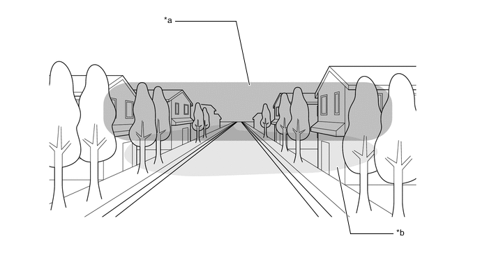
*a Area Illuminated by High Beams *b Area Illuminated by Low Beams Figure 2. Normal Mode
*a Area Illuminated by High Beams *b Area Illuminated by Low Beams Figure 3. High Speed Mode
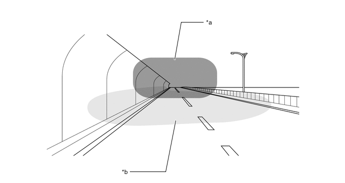
*a Area Illuminated by High Beams *b Area Illuminated by Low Beams -
-
Light Disable Control Function
-
The light disable control function dims LEDs in the high beam headlight accordingly when the forward recognition camera (camera sensor) detects a preceding vehicle or an oncoming vehicle.
-
The LED Light Control Computer and LED unit enable the LEDs of the headlight assembly to be dimmed independently as necessary.
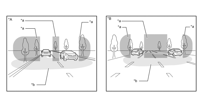
*A When driving on road with one lane in each direction *B When driving on a multi-lane road *a Area Illuminated by High Beams *b Area Illuminated by Low Beams -
-
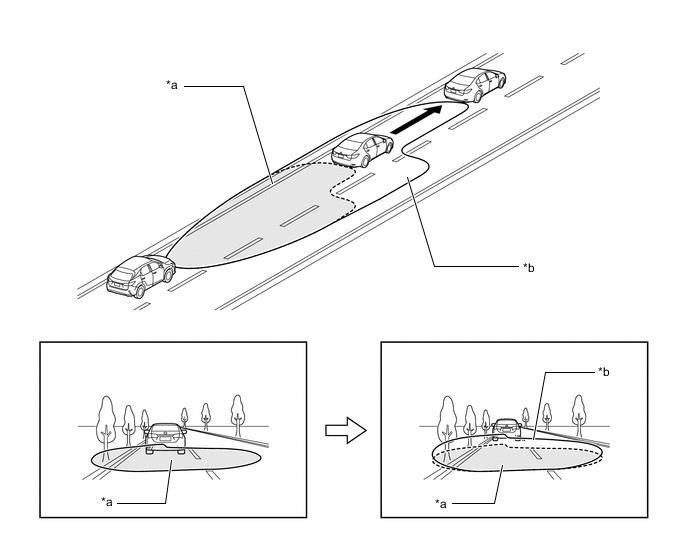
Headlight Swivel Control Function
-
The headlight swivel control function adjusts the brightness of headlights while turning a corner to ensure excellent visibility.
*a Area Illuminated by High Beams *b Area Illuminated by Low Beams -
-
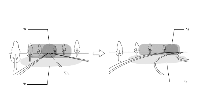
Cut-off Line Tilt Control Function
-
The cut-off line tilt function controls the leveling motor built into the headlight assembly to optimize the illumination area of the low beams in accordance with the distance to the preceding vehicle detected by the forward recognition camera (camera sensor).
*a Illumination Area of Low Beams without Control *b Illumination Area of Low Beams during Control -
-
-
DIAGNOSIS
-
When the main body ECU (multiplex network body ECU) detects a malfunction in the automatic high beam control system, Diagnostic Trouble Codes (DTCs) are stored in memory.
-
The DTCs can be read using the Global TechStream (GTS). For details, refer to the Repair Manual.
-