ELECTRIC PARKING BRAKE SYSTEM
-
CONSTRUCTION
-
The parking brake actuator with bracket assembly is constructed with a motor, each gear, emergency release gear, clutch, shaft, equalizer and tension sensor, and is connected to each cable.
-
When a lock signal is received from the parking brake ECU assembly, the motor will wind up the parking brake cable by rotating the shaft, thus locking the parking brake.
-
When the motor stops rotating, operation of the clutch maintains the pulling force of the parking brake cable.
-
When a release signal is received from the parking brake ECU assembly, the motor turns in the opposite direction to reduce the pulling force of the parking brake cable, thus releasing the parking brake.
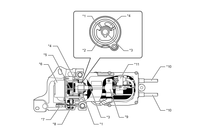
*1 Clutch *2 Cam *3 Shaft *4 No. 3 Gear *5 No. 2 Gear *6 Motor *7 Emergency Release Cable *8 Emergency Release Gear *9 Equalizer *10 Parking Brake Cable *11 Tension Sensor - - Figure 1. Operation Image
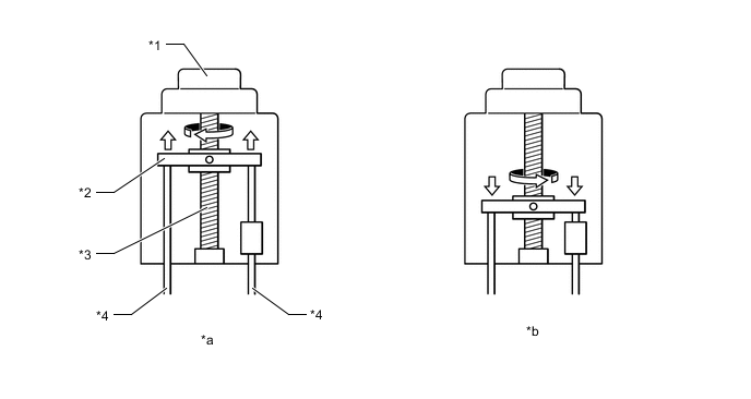
*1 Motor *2 Equalizer *3 Shaft *4 Parking Brake Cable *a Parking Brake Lock *b Parking Brake Release
-
-
OPERATION
-
Manual Release
-
If the electric parking brake system fails, the parking brake can be released manually through the use of a dedicated tool that is onboard the vehicle. To do so, the emergency release cable must be turned counterclockwise while the emergency release cable is pushed. As the emergency release cable is pushed, the rotational movement of the emergency release cable travels to the emergency release gear. Then, the No. 2 and No. 3 gears rotate the shaft in order to loosen the parking brake cable.
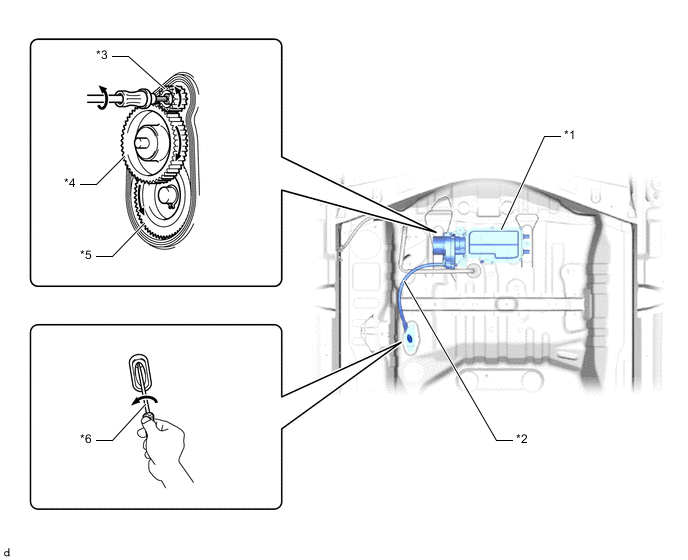
*1 Parking Brake Actuator with Bracket Assembly *2 Emergency Release Cable *3 Emergency Release Gear *4 No. 2 Gear *5 No. 3 Gear *6 Dedicated Tool
-
-