BRAKE CONTROL SYSTEM
-
CONSTRUCTION
-
The brake actuator assembly consists of the brake actuator portion and skid control ECU.
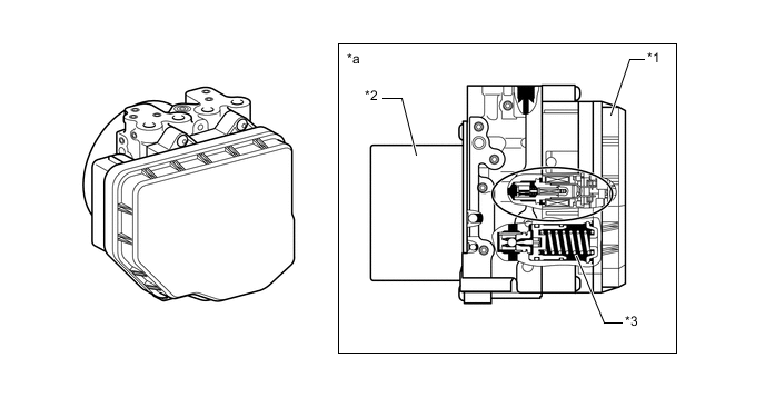
*1 Skid Control ECU Portion *2 Motor Portion *3 Reservoir Portion - - *a Cross Section - - -
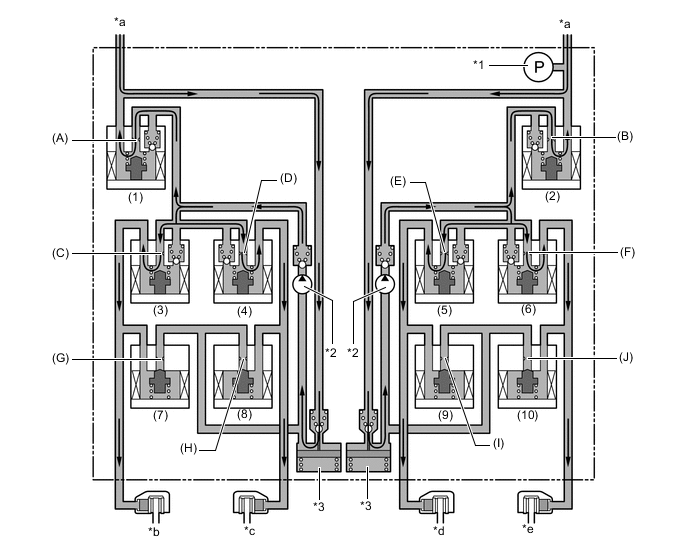
The brake actuator portion consists of 2 master cylinder cut solenoid valves, 4 pressure holding solenoid valves, 4 pressure reduction solenoid valves, 2 pumps, 2 reservoirs and a master cylinder pressure sensor.
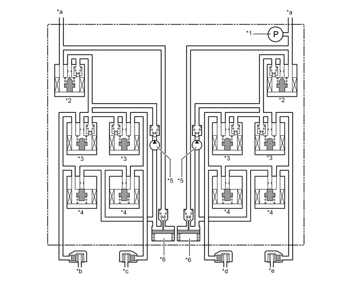
*1 Master Cylinder Pressure Sensor *2 Master Cylinder Cut Solenoid Valve *3 Pressure Holding Solenoid Valve *4 Pressure Reduction Solenoid Valve *5 Pump *6 Reservoir *a From Master Cylinder *b Front Brake RH *c Front Brake LH *d Rear Brake RH *e Rear Brake LH - -
-
-
OPERATION
-
ABS and EBD
-
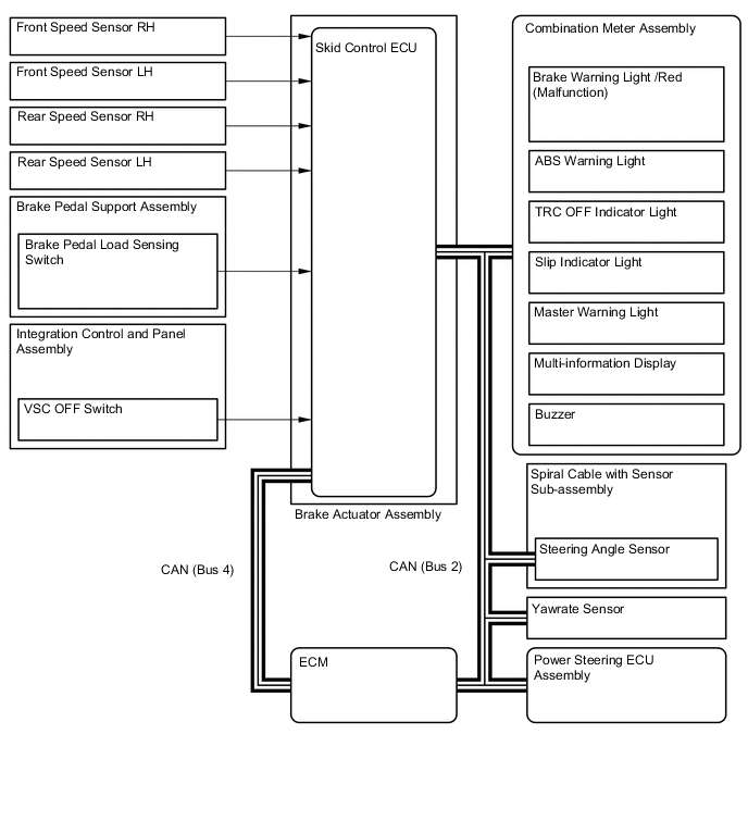
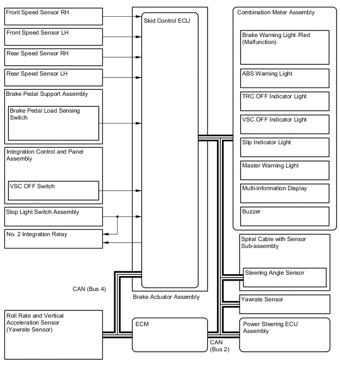
Based on the signals received from the 4 speed sensors, the skid control ECU calculates the speed of each wheel, and checks the wheel slipping conditions. In accordance with the slipping condition, the skid control ECU controls each solenoid valve in the brake actuator assembly in order to adjust the fluid pressure of each wheel cylinder in the following 3 modes: pressure increase, pressure holding and pressure reduction modes.
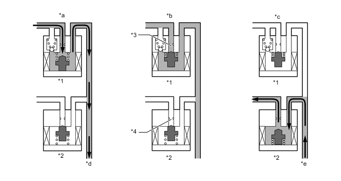
*1 Pressure Holding Solenoid Valve *2 Pressure Reduction Solenoid Valve *3 Port A *4 Port B *a Pressure Increase Mode *b Pressure Holding Mode *c Pressure Reduction Mode *d To Wheel Cylinder *e From Wheel Cylinder - - Brake Actuator Assembly Operation in ABS and EBD Item Pressure Increase Mode Pressure Holding Mode Pressure Reduction Mode Pressure Holding Solenoid Valve (Port A) Off (Open) On (Closed) On (Closed) Pressure Reduction Solenoid Valve (Port B) Off (Closed) Off (Closed) On (Open) Wheel Cylinder Pressure Increases Holds Reduces
-
-
Brake Assist
-
In the event of emergency braking, the skid control ECU determines the driver's intention based on the speed of the pressure increase in the master cylinder determined by the master cylinder pressure sensor signal. If the skid control ECU judges the need for additional brake assist, pressure is generated by the pump in the brake actuator assembly and directed to the wheel cylinder to apply a large amount of fluid pressure.
*1 Master Cylinder Pressure Sensor *2 Pump *3 Reservoir - - *a From Master Cylinder *b Front Brake RH *c Front Brake LH *d Rear Brake RH *e Rear Brake LH - - Brake Actuator Assembly Operation in Brake Assist Item Brake Assist Not Activated Brake Assist Activated Pump Off On Master Cylinder Cut Solenoid Valve (1) Port (A) Off (Open) On* (2) Port (B) Off (Open) On* Pressure Holding Solenoid Valve (3) Port (C) Off (Open) Off (Open) (4) Port (D) Off (Open) Off (Open) (5) Port (E) Off (Open) Off (Open) (6) Port (F) Off (Open) Off (Open) Pressure Reduction Solenoid Valve (7) Port (G) Off (Closed) Off (Closed) (8) Port (H) Off (Closed) Off (Closed) (9) Port (I) Off (Closed) Off (Closed) (10) Port (J) Off (Closed) Off (Closed) Tech Tips
*: The solenoid valve switches the hydraulic pressure between "open" and "closed" in accordance with the operating conditions by adjusting continually.
-
-
TRC
-
The fluid pressure generated by the pump is regulated by the master cylinder cut solenoid valve to the required pressure. Thus, the wheel cylinders of the drive wheels are controlled in the following 3 modes: pressure increase, pressure holding and pressure reduction modes to control the slippage of the drive wheels. Each pressure holding solenoid valve and the pressure reduction solenoid valve is turned on or off in accordance with the ABS and EBD operation patterns.
*1 Master Cylinder Pressure Sensor *2 Pump *3 Reservoir - - *a From Master Cylinder *b Front Brake RH *c Front Brake LH *d Rear Brake RH *e Rear Brake LH - - Brake Actuator Assembly Operation in TRC Item TRC Operation Not Activated Pressure Increase Mode Pressure Holding Mode Pressure Reduction Mode Pump Off On On On Master Cylinder Cut Solenoid Valve (1) Port (A) Off (Open) Off (Open) Off (Open) Off (Open) (2) Port (B) Off (Open) On* On* On* Front Brake Pressure Holding Solenoid Valve (3) Port (C) Off (Open) On (Closed) On (Closed) On (Closed) (4) Port (D) Off (Open) On (Closed) On (Closed) On (Closed) Pressure Reduction Solenoid Valve (7) Port (G) Off (Closed) Off (Closed) Off (Closed) Off (Closed) (8) Port (H) Off (Closed) Off (Closed) Off (Closed) Off (Closed) Wheel Cylinder Pressure Right - - - - Left - - - - Rear Brake Pressure Holding Solenoid Valve (5) Port (E) Off (Open) On* On (Closed) On (Closed) (6) Port (F) Off (Open) On* On (Closed) On (Closed) Pressure Reduction Solenoid Valve (9) Port (I) Off (Closed) Off (Closed) Off (Closed) On (Open) (10) Port (J) Off (Closed) Off (Closed) Off (Closed) On (Open) Wheel Cylinder Pressure Right - Increases Holds Reduces Left - Increases Holds Reduces Tech Tips
*: The solenoid valve switches the hydraulic pressure between "open" and "closed" in accordance with the operating conditions by adjusting continually.
-
-
VSC
-
The VSC, by the way of solenoid valves, controls fluid pressure generated by the pump and applies it to the brake wheel cylinder of each wheel in the following 3 modes: pressure increase, pressure holding and pressure reduction modes. As a result, the tendency of front wheel skid or rear wheel skid is controlled.
-
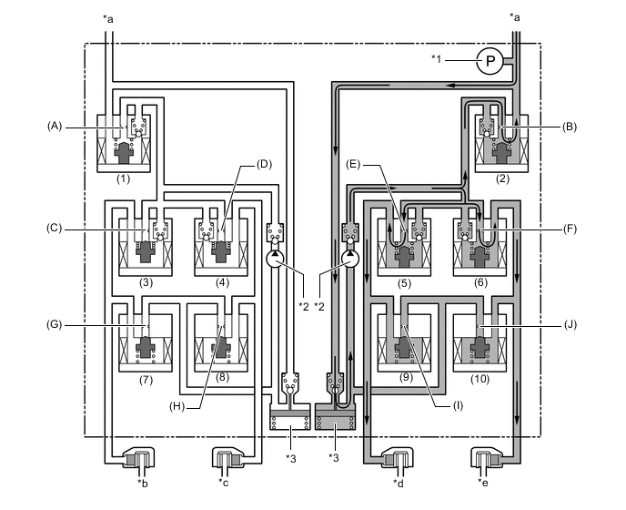
In front wheel skid restraining control, the brakes of the front wheel on the outer circle of the turn and the rear wheels are applied. Also, depending on whether the brake is on or off and also depending on the condition of the vehicle, there are circumstances in which the brake might not be applied to the wheels even if the wheel is targeted for braking. The following diagram shows the hydraulic circuit in pressure increase mode as it controls a front wheel skid condition while the vehicle is making a right turn. In other operating modes, the pressure holding valve and the pressure reduction valve are turned on or off in accordance with the ABS and EBD operation patterns.
*1 Master Cylinder Pressure Sensor *2 Pump *3 Reservoir - - *a From Master Cylinder *b Front Brake RH *c Front Brake LH *d Rear Brake RH *e Rear Brake LH - - Brake Actuator Assembly Operation in VSC (Front Wheel Skid Restraining) Item VSC Operation Not Activated Pressure Increase Mode Pressure Holding Mode Pressure Reduction Mode Pump Off On On On Master Cylinder Cut Solenoid Valve (1) Port (A) Off (Open) On* On* On* (2) Port (B) Off (Open) On* On* On* Front Brake Pressure Holding Solenoid Valve (3) Port (C) Off (Open) On (Closed) On (Closed) On (Closed) (4) Port (D) Off (Open) On* On (Closed) On (Closed) Pressure Reduction Solenoid Valve (7) Port (G) Off (Closed) Off (Closed) Off (Closed) Off (Closed) (8) Port (H) Off (Closed) Off (Closed) Off (Closed) On (Open) Wheel Cylinder Pressure Right - - - - Left - Increases Holds Reduces Rear Brake Pressure Holding Solenoid Valve (5) Port (E) Off (Open) On* On (Closed) On (Closed) (6) Port (F) Off (Open) On* On (Closed) On (Closed) Pressure Reduction Solenoid Valve (9) Port (I) Off (Closed) Off (Closed) Off (Closed) On (Open) (10) Port (J) Off (Closed) Off (Closed) Off (Closed) On (Open) Wheel Cylinder Pressure Right - Increases Holds Reduces Left - Increases Holds Reduces Tech Tips
*: The solenoid valve switches the hydraulic pressure between "open" and "closed" in accordance with the operating conditions by adjusting continually.
-
During the rear wheel skid restraining control, the brakes of the front and rear wheels on the outer circle of the turn are applied. Also, depending on whether the brake is on or off and also depending on the condition of the vehicle, there are circumstances in which the brake might not be applied to the wheels even if the wheel is targeted for braking. The following diagram shows the hydraulic circuit in pressure increase mode, as it controls the rear wheel skid condition while the vehicle is making a right turn. In other operating modes, the pressure holding valve and the pressure reduction valve are turned on or off in accordance with the ABS and EBD operation patterns.
*1 Master Cylinder Pressure Sensor *2 Pump *3 Reservoir - - *a From Master Cylinder *b Front Brake RH *c Front Brake LH *d Rear Brake RH *e Rear Brake LH - - Brake Actuator Assembly Operation in VSC (Rear Wheel Skid Restraining) Item VSC Operation Not Activated Pressure Increase Mode Pressure Holding Mode Pressure Reduction Mode Pump Off On On On Master Cylinder Cut Solenoid Valve (1) Port (A) Off (Open) On* On* On* (2) Port (B) Off (Open) On* On* On* Front Brake Pressure Holding Solenoid Valve (3) Port (C) Off (Open) On (Closed) On (Closed) On (Closed) (4) Port (D) Off (Open) On* On (Closed) On (Closed) Pressure Reduction Solenoid Valve (7) Port (G) Off (Closed) Off (Closed) Off (Closed) Off (Closed) (8) Port (H) Off (Closed) Off (Closed) Off (Closed) On (Open) Wheel Cylinder Pressure Right - - - - Left - Increases Holds Reduces Rear Brake Pressure Holding Solenoid Valve (5) Port (E) Off (Open) On (Closed) On (Closed) On (Closed) (6) Port (F) Off (Open) On* On (Closed) On (Closed) Pressure Reduction Solenoid Valve (9) Port (I) Off (Closed) Off (Closed) Off (Closed) Off (Closed) (10) Port (J) Off (Closed) Off (Closed) Off (Closed) On (Open) Wheel Cylinder Pressure Right - - - - Left - Increases Holds Reduces Tech Tips
*: The solenoid valve switches the hydraulic pressure between "open" and "closed" in accordance with the operating conditions by adjusting continually.
-
-
Steering Cooperative Control
-
The operation of the solenoid valves under the steering cooperative control is the same as the TRC or VSC operation.
-
-
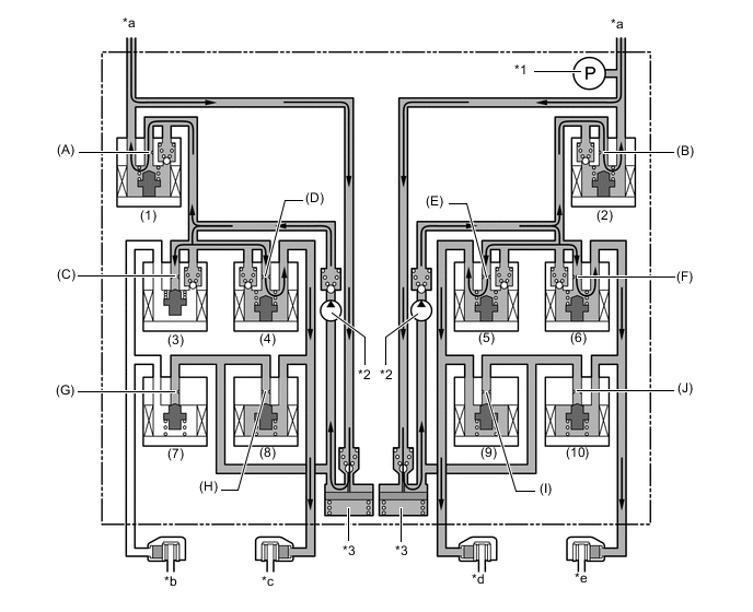
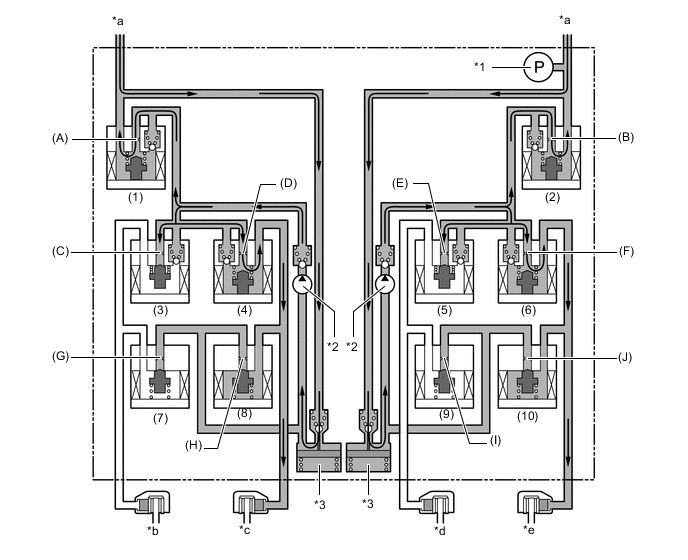
Hill-start Assist Control
-
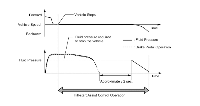
Hill-start assist control controls the brakes by maintaining the master cylinder fluid pressure produced by depressing the brake pedal.
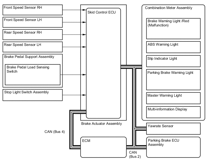
Figure 1. Example of Hill-start Assist Control when Climbing Uphill with Shift Lever in D (Driver Depresses Accelerator Pedal to Start Off after Hill-start Assist Control Operation)
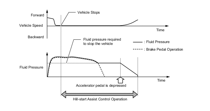
Figure 2. Example of Hill-start Assist Control when Climbing Uphill with Shift Lever in D (Driver Takes No Action after Hill-start Assist Control Operation)

*1 Master Cylinder Pressure Sensor *2 Pump *3 Reservoir - - *a From Master Cylinder *b Front Brake RH *c Front Brake LH *d Rear Brake RH *e Rear Brake LH - - Brake Actuator Assembly Operation in Hill-start Assist Control Item Hill-start Assist Control Operation Not Activated Pressure Holding Mode Pressure Reduction Mode Pump Off On On Master Cylinder Cut Solenoid Valve (1) Port (A) Off (Open) On* On* (2) Port (B) Off (Open) On* On* Front Brake Pressure Holding Solenoid Valve (3) Port (C) Off (Open) Off (Open) Off (Open) (4) Port (D) Off (Open) Off (Open) Off (Open) Pressure Reduction Solenoid Valve (7) Port (G) Off (Closed) Off (Closed) Off (Closed) (8) Port (H) Off (Closed) Off (Closed) Off (Closed) Wheel Cylinder Pressure Right - Holds Reduces Left - Holds Reduces Rear Brake Pressure Holding Solenoid Valve (5) Port (E) Off (Open) Off (Open) Off (Open) (6) Port (F) Off (Open) Off (Open) Off (Open) Pressure Reduction Solenoid Valve (9) Port (I) Off (Closed) Off (Closed) Off (Closed) (10) Port (J) Off (Closed) Off (Closed) Off (Closed) Wheel Cylinder Pressure Right - Holds Reduces Left - Holds Reduces Tech Tips
*: The solenoid valve switches the hydraulic pressure between "open" and "closed" in accordance with the operating conditions by adjusting continually.
-
-
Radar Cruise Control Brake (Models with Lexus Safety System +)
-
The skid control ECU operates the brakes by receiving a motive force request signal from the driving support ECU assembly while the dynamic radar cruise control system is activated. This brake control operates in the same way as a normal brake operation.
-
-
Pre-crash Brake (Models with Lexus Safety System +)
-
If the driving support ECU assembly determines that the possibility of a collision is high, the ECU sends a pre-crash brake assist request signal to the skid control ECU. Upon receiving the signal, the skid control ECU switches the brake assist to standby mode. When the driver depresses the brake pedal, the skid control ECU operates the brake assist based on the master cylinder pressure sensor.
-
If a collision is unavoidable, the skid control ECU actuates the motor in the power supply portion to apply direct pressure to the wheel cylinders even if the driver does not depress the brake pedal. This brake control operates in the same way as a normal brake operation.
-
-