TORQUE VECTORING DIFFERENTIAL SYSTEM
-
FUNCTION OF MAIN COMPONENTS
Component Function Torque Vectoring Differential ECU Assembly Detects the vehicle driving conditions based on the signals from switches, sensors and ECUs and controls the torque vectoring differential motor sub-assembly to distribute the optimal amount of torque to each rear wheel to suit the driving conditions. Torque Transfer Module Motor Sub-assembly Distributes torque based on signals from the torque vectoring differential ECU assembly. Torque Transfer Module Motor Sub-assembly Motor Rotational Angle Sensor Detects the motor angle of the torque transfer module motor sub-assembly using a revolution sensor (resolver). ECM Outputs signals such as the throttle position signal, engine speed signal, shift position signal, and shift range signal to the torque vectoring differential ECU assembly via CAN communication. Brake Actuator Assembly Skid Control ECU Receives signals from the speed sensors and stop light switch assembly and sends them to the torque vectoring differential ECU assembly via CAN communication. Accelerator Pedal Sensor Assembly Detects the accelerator pedal opening angle. Crank Position Sensor Detects the engine speed. Yawrate Sensor Detects the vehicle yaw rate, and longitudinal and lateral acceleration. Spiral Cable with Sensor Sub-assembly Steering Sensor Detects the steered direction and angle of the steering wheel and sends it to the torque vectoring differential ECU assembly via CAN communication. Speed Sensor Detects the wheel speed of each of the 4 wheels. Temperature Sensor Detects the temperature of the ATF fluid in the torque transfer module. Park/Neutral Position Switch Assembly Detects the shift lever position. Stop Light Switch Assembly Detects when the brake pedal is depressed. Combination Switch Assembly TVD Switch Selects the Torque Vectoring Differential control mode. Combination Meter Assembly Torque Vectoring Differential Control Mode Indicator Displays the current Torque Vectoring Differential control mode. Multi-information Display
-
Displays the amount of torque applied to each rear wheel and the distribution of torque controlled by the Torque Vectoring Differential system.
-
Displays a warning message to warn the driver when a malfunction or overheating is detected in the Torque Vectoring Differential system.
Master Warning Light Warns the driver by sounding a buzzer and illuminating the master warning light when a malfunction or overheating is detected in the Torque Vectoring Differential system. Buzzer -
-
SYSTEM CONTROL
Electronic Control of Torque Vectoring Differential Control Function Steering Angle Feed-Forward Control Distributes torque between each rear wheel to assist steering, improving steering response. LSD Control during Deceleration Optimally distributes torque between each rear wheel during deceleration, ensuring braking stability similar to that provided by the Limited Slip Differential (LSD). LSD Control during Countersteer* Determines whether the vehicle is in a countersteer state and distributes torque to the outer rear wheel of the turn, ensuring vehicle controllability, similar to that provided by the Limited Slip Differential (LSD). Yawrate Feedback Control Distributes torque between each rear wheel so that the difference between the ideal yaw rate and actual yaw rate (during both oversteer and understeer) is eliminated, improving the ability of the vehicle to follow the desired driving line during acceleration and deceleration. Differential Rotation Suppression Control Distributes torque between each rear wheel so that an excessive difference in rotation between the rear wheels can be eliminated, ensuring traction performance when one wheel is slipping. Cooperated Control with VDIM Optimally controls the Torque Vectoring Differential system and the brake force of the VDIM system based on the ideal yaw rate, ensuring vehicle stability. *: Operates when in Expert mode or when the VSC is disabled.
-
FUNCTION
-
Torque Vectoring Differential Control
-
Control when Entering a Corner
-
Torque is transferred from the inner rear wheel of the turn to the outer rear wheel, generating a yaw moment in the direction of the turn, achieving excellent turn-in and braking stability.
Figure 1. When turning left
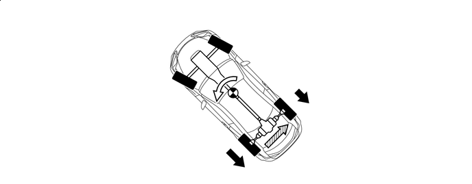

Coast Torque 
Yaw Moment 
Torque Transfer - -
-
-
Control while Turning
-
When the vehicle is entering a corner, torque is transferred from the inner rear wheel of the turn to the outer rear wheel to improve the vehicles turning ability. As the vehicle progresses through the turn the amount of torque transferred to the outer rear wheel is gradually increased. This generates a yaw moment in the direction of the turn reducing the required steering amount, contributing to improved steering response.
Figure 2. When turning left
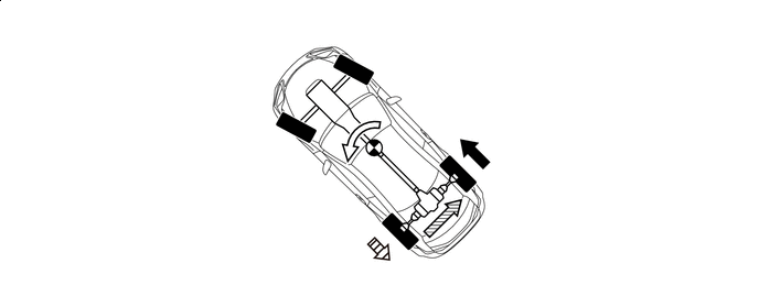
Drive Torque Yaw Moment Torque Transfer 
Coast Torque
-
-
Control when Exiting a Corner
-
While turning and exiting from a corner, torque to the outer rear wheel is continually increased enabling the vehicle to exit the corner smoothly while maintaining good vehicle balance and handling performance.
-
Torque is optimally distributed between each rear tire in order to maximize traction so that the vehicle exits the corner smoothly.
Figure 3. When turning left
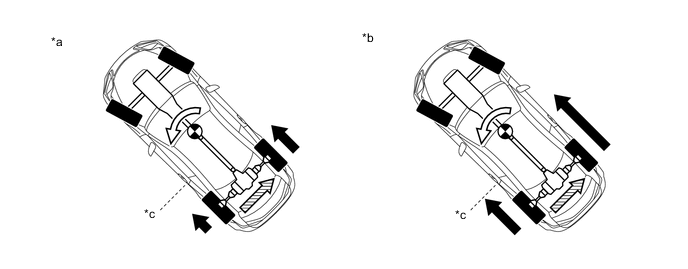
*a Small Amount of Acceleration *b Large Amount of Acceleration *c Tire Grip Limit on Inner Wheel - - Drive Torque Yaw Moment Torque Transfer - -
-
-
-
-
FAIL-SAFE
-
When a malfunction is detected in the Torque Vectoring Differential system or there is a possibility of damage to the drive-train, the system enters fail-safe mode and warns the driver.
-
When Torque Vectoring Differential system is malfunctioning
-
When a malfunction is detected in the Torque Vectoring Differential system, control by the Torque Vectoring Differential system is canceled, the system sounds the buzzer in the combination meter assembly, turns off the torque vectoring differential control mode indicator, and illuminates the master warning light. Additionally, the warning message "TVD System Malfunction. Visit Your Dealer." is displayed on the multi-information display.
Tech Tips
When control by the Torque Vectoring Differential system is canceled, the basic functions of the differential system are performed enabling the vehicle to be driven.
-
-
When Torque Vectoring Differential System is Overheating
-
If the temperature of the oil in the torque transfer module becomes excessively high such as when driving for a long time under extremely high load conditions, the system sounds the buzzer in the combination meter assembly and illuminates the master warning light. Additionally, the warning message "TVD System Overheated. Reduce Engine Speed and Load." is displayed on the multi-information display.
Tech Tips
When the oil temperature drops below a specified level, warnings are automatically canceled.
-
-
-
-
DIAGNOSIS
-
The torque vectoring differential ECU assembly will also store the Diagnostic Trouble Codes (DTCs) of the malfunctions. The DTCs stored in the torque vectoring differential ECU assembly are output to the Global TechStream (GTS) via the torque vectoring differential ECU assembly and the DLC3. For details, refer to the Repair Manual.
-