TORQUE VECTORING DIFFERENTIAL SYSTEM
-
OPERATION
-
Torque Vectoring Differential Control Mode Change Function
-
Torque Vectoring Differential control modes can be changed via switch operation.
-
3 Torque Vectoring Differential control modes are provided. The Torque Vectoring Differential control mode is not linked to the drive mode select, enabling the driver to select the Torque Vectoring Differential control mode independently.
-
The currently selected Torque Vectoring Differential control mode is displayed on the combination meter. When the mode is changed, an image is displayed on the multi-information display.
Torque Vectoring Differential Control Mode Outline STANDARD Mode Default mode. Realizes ideal vehicle behavior with a high level of both agility and stability. SLALOM Mode Places emphasis on steering response. Realizes agility expected of a smaller vehicle. TRACK Mode Places emphasis on stability during high-speed circuit driving, with tuning that enables acceleration with confidence. Figure 1. LHD Models
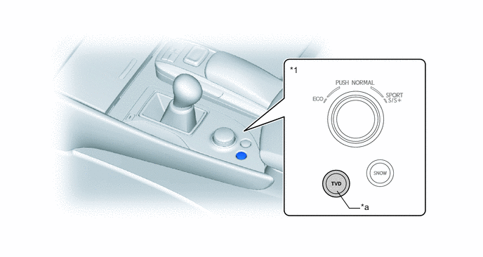
*1 Combination Switch Assembly - - *a TVD Switch - - Figure 2. RHD Models
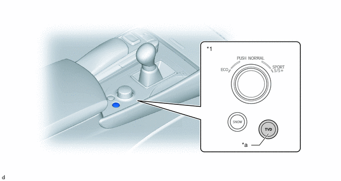
*1 Combination Switch Assembly - - *a TVD Switch - -
-
-
Display Function of Torque Vectoring Differential Control Operation Condition
-
The Torque Vectoring Differential control state is displayed on the multi-information display to provide information to the driver. The amount of torque applied to each rear wheel and the torque balance are shown.
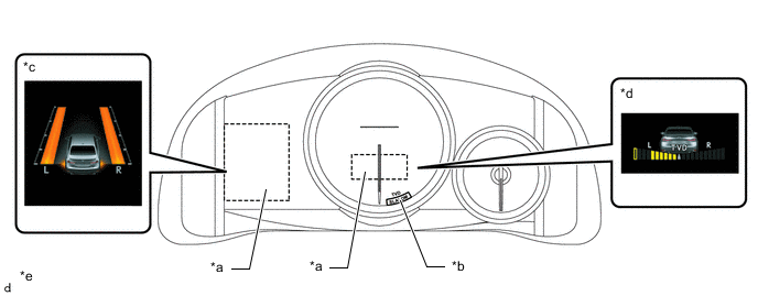
*a Multi-information Display *b Torque Vectoring Differential Control Mode Indicator *c Amount of Torque Applied to Each Rear Wheel *d Balance of Torque Distributed due to Torque Vectoring Differential Control *e This illustration is an example. - -
-
-